I've used ECC40 before and it's a really good indirectly heated tube - the origin of the E80CC. But in PP I'd stay with DHTs and look at 3a5 and 1J6. I've used both of those before and they're both excellent - better than ECC40 to my ears. 3a5 to 1J6 would probably do very nicely. In fact that's rather a good idea. But if I could use the PP LL1689 in SE at 3 or 4ma I'd still prefer to go with a 26.
Never!
A compound triode - bipolar stage, with a 2nd-order dc bias controller, to give zero dc offset, no output capacitor at all.
I'll finish drawing it, if there's interest.
+1
")
I've used ECC40 before and it's a really good indirectly heated tube - the origin of the E80CC. But in PP I'd stay with DHTs and look at 3a5 and 1J6. I've used both of those before and they're both excellent - better than ECC40 to my ears. 3a5 to 1J6 would probably do very nicely. In fact that's rather a good idea. But if I could use the PP LL1689 in SE at 3 or 4ma I'd still prefer to go with a 26.
As you like of course. For me ECC40 is the by far best of the those and I do prefer Class A PP. Only the 26 can be marginally better in terms of linearity but requires a lot more care in filament supply and is a poor choice in terms of efficiency. The E80CC, regardless of its presentation as a SQ valve, is nowhere near the ECC40 from any point of view.
Cheers
Never!
A compound triode - bipolar stage, with a 2nd-order dc bias controller, to give zero dc offset, no output capacitor at all.
I'll finish drawing it, if there's interest.
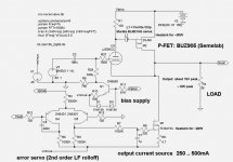
Here's my serving suggestion, for any DIYers who don't like the cost of a real transformer. The 4P1L + Sowter is very appealing, but any compromise on the transformer will bring disappointment.
Don't be put off by the transistors in this drawing.
Q1 is a little bias source.
Q3 and Q4 are an error servo, with a 2nd-order sub-audio filter. These keep the output within a few mV of ground, without interacting with the music.
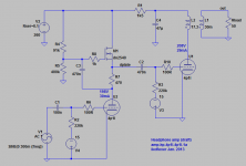
M1 is a class-A current sink, set at 250-500mA, depending on the desired peak current into the headphones. Please trade off the peak current capability with the idle power burn. (15 - 30W each in M1 and M2).
The actual output stage is a new JJ E88CC running at 60V and 10mA. It's a cathode follower - but assisted by the audio FET BUZ905, made by Semelab.
The BUZ905 is simply carrying any current demand, above the 10mA standing current in the E88CC. The linearity is much better than a normal cathode follower, because the load variation is so small.
The BUZ905 is chosen because of the high power handling of the TO3 package, and the zero-TC (temperature coefficient) which occurs at < 0,5A (rather than the whole amperes needed by the usual switching FETs). This ensures that the idle current is stable, even at intervals faster than the servo can control it.
The E88CC is chosen, because it has high gm (for good follower performance), and because it likes low voltage. I don't think the 4P1L would work well here.
The overall cost of parts is relatively low, and the performance is very high. No capacitors, chokes, or transformers are needed in the output, because the BUZ905 is performing the impedance transformation from the E88CC to 38 ohms.
Attachments
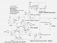
4P1L would not like the low +60V supply. You could increase the supply to 100V, and although the 4P1L might work better, the power burn in the BUZ905 would then be 25-50W.
Going further into the class-A room heater world, you could upgrade to the more expensive BUZ906 and up the supply to 150V, if the 4P1L likes that better. the BUZ906 heatsink would then need to handle 40-75W in this case!
But it would still have a gain of almost 1, like the E88CC version. So you can drive it with whatever stage gives the peak voltage you need, for the headphones it used with.
If 3V peak is high enough, you can connect directly to a DAC-level output. The input capacitance is very low, since Mr Miller has been denied access to this party.
A class A PP 4P1L all DHT design would be interesting it could double as a nice speaker amp and also power HE-6's..
The original Class A PP amp in the datasheet uses 30K plate-to-plate and about 5 mA for 0.5W Pout while the single ended version uses 15K at 250V/6mAfor .28W Pout.
But I don't know about the filaments do the Coleman regs work with PP, if so how?
Good question.Wow - good work. How would this work with a 4P1L? Would it need 2 stages?
Rod, I appreciate the input but there are a million hybrid headphone amp designs out there and none of them are DHT, neither is yours. In fact I bought a used "Lyr" for $250 that performs just as well as what you posted, so there is zero incentive to DIY another indirect heated hybrid.
Change that tube to a #26 or something DHT and at least make an attempt to contribute to the thread subject

Btw is a Buz905 a lateral ? I am just busting your balls a little, we wouldn't even be TALKING about an all DHT headphone amp were not for you and iko sharing your filament power designs
On another subject in my quest for an output transformer this company got back to me. http://goldenmiddle.com/images/is6.pdf Looks interesting sort of old school preampish transformers, I think I'm reading that the primary is 3K which would work for PSE 4p1l or 2A3. Price is $230 eur not including postage.
One thing I am afraid of is investing in quality OPT's and then in a few months wanting to hook the amp up to the pair of Fostex127E's I have hidden in the garage, or one day I open our local classifieds and I see a pair of Klipsch La Scala's for $100. I don't think it would be too much scope-creep to want an 8 ohm tap on the secondary ?
Btw I also think it is possible to DC couple #26 to 4P1l and still use filament bias, here the cap under the 4p1l is below the signal and just for noise reduction, I think it can be left out.
Attachments
Last edited:
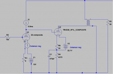
Well, it does actually work quite well with a 4P1L. The triode curves and Dmitry's model suggest around -3.5V bias allows operation as low as 70V, which should be fine. A little more class A power dissipation, but you have your DHT.
BTW, please don't confuse this circuit with the usual "tube hybrid" circuit. The kind where a triode stage has a source follower stuck on the output.
My circuit centres on a compound-device, with the FET acting as a current-amplifying slave for the cathode follower. The FET only pumps current, at high dynamic impedance - until the cathode follower is satisfied.
The (triode) cathode current varies by only a fraction of the load current, allowing the dynamic output impedance to remain almost constant throughout the swing. This is quite different from the usual follower circuits, where output Z has a strong dependency on load current. If you like LOW and CONSTANT output impedance, this circuit takes some beating.
The FET type: yes, it's a lateral - a derived version of the Hitachi 2SJ50 and successors.
Attachments
were not for you and iko sharing your filament power designs
Just want to clarify that what I posted earlier is NOT Rod's design. As far as I know his schematics are not in the open domain. My circuit uses a cap multiplier, not a gyrator, and a CCS. Just sayin'!
Back to the headphone amp. I really don't see the reason to a load impedances in the speaker range. There are plenty of very good power amps of low power that will cover that range. I'd say that an amp that can do 50 ohm loads and 300 ohm loads will cover lots of headphones. I'm working on a DHT amp for a 50-60 ohm load because those are the headphones that I have, and I'll post my results here. With a different output transformer a 100, 200, or 300 ohm load would be just as easy to drive.
Regarding playing headphones off different impedances. I would say the best is changing arrangements of multiple secondary windings: with three windings and a rotary switch one can do a lot as shown in the links (not authored by me).
Sowter Type 8650 Headphone Output transformer (for a probably nice OPT)
AÜ_Hinweise (for changing between impedances)
Sowter Type 8650 Headphone Output transformer (for a probably nice OPT)
AÜ_Hinweise (for changing between impedances)
Here's my draft, using the 4P1L, since it was the topic of discussion lately. I have a good stash of 4P1L and plan to do something with it. Simpler circuits appeal to me, hence my preference for this. It's easy enough to replace the gyrator and coupling cap with an IT.
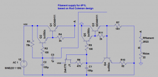
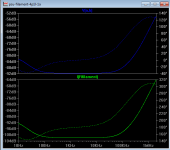
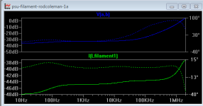
In reality I will implement filament bias via the attached circuit which worked very very well in my 26 preamp. I developed this circuit independently but it's just been pointed to me that it'is almost identical to Rod's older version that he posted in this forum, so credit deservedly belongs to Rod Coleman. Almost identical does not mean it is the same. Small changes can make a big difference in performance. In simulation Rod's older circuit can bring a 1V ripple at the input 32dB down to 25mV. Small changes in the circuit make it bring the 1V input ripple 92dB down, to 25uV. I will not belabour the point, I'm sure that his new circuit is a huge improvement over the circuit he posted in the link below. All I wanted to do is to offer an alternative which, based on my experience, is excellent in performance and simple to implement.
http://www.diyaudio.com/forums/tubes-valves/38248-new-dht-heater-7.html#post2024952 While we're at it, I want to say that Rod's kit is really good value.
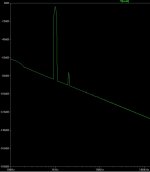
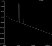
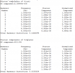
Edit: the thd results, for what it's worth, are at 1kHz, and about 2.2V p-p into the 50R load. Also, there might be better operating points for this tube, but I didn't look too hard.
In reality I will implement filament bias via the attached circuit which worked very very well in my 26 preamp. I developed this circuit independently but it's just been pointed to me that it'is almost identical to Rod's older version that he posted in this forum, so credit deservedly belongs to Rod Coleman. Almost identical does not mean it is the same. Small changes can make a big difference in performance. In simulation Rod's older circuit can bring a 1V ripple at the input 32dB down to 25mV. Small changes in the circuit make it bring the 1V input ripple 92dB down, to 25uV. I will not belabour the point, I'm sure that his new circuit is a huge improvement over the circuit he posted in the link below. All I wanted to do is to offer an alternative which, based on my experience, is excellent in performance and simple to implement.
http://www.diyaudio.com/forums/tubes-valves/38248-new-dht-heater-7.html#post2024952 While we're at it, I want to say that Rod's kit is really good value.
Edit: the thd results, for what it's worth, are at 1kHz, and about 2.2V p-p into the 50R load. Also, there might be better operating points for this tube, but I didn't look too hard.
Attachments
A compound triode - bipolar stage, with a 2nd-order dc bias controller, to give zero dc offset, no output capacitor at all.
I like that idea. One could also be completely blasphemic and use something like an LME49600 headphone buffer amp on the output with a triode on the input to provide a gain of a few V/V.
~Tom
I like that idea. One could also be completely blasphemic and use something like an LME49600 headphone buffer amp on the output with a triode on the input to provide a gain of a few V/V.
~Tom
It will be fun to try out some of these 'sand-assisted triode' ideas.
This is definitely the route to follow, unless you are prepared to spend the money on a properly-specified, AND high quality transformer (in this case, the Sowter) - and a no-compromise set of power supplies. DHTs need a high-quality environment to show their worth.
Using a DHT with a cheap transformer, or power supply cost-cutting - is certain to be a disappointment, that will easily be embarrassed by all-SS solutions.
- Home
- Amplifiers
- Tubes / Valves
- The all DHT SET Headphone Amp