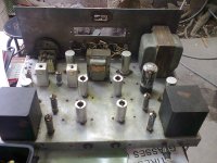
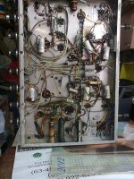
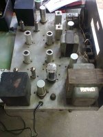
I Bought this 6AQ5-12au7-12ax7 DIY tubeamp from a seller for 85USD, it's still operational and plays music but not to my liking...maybe because of old caps and components needs to be upgraded. It's 10w pp amp with 4 6aq5 as output...I plant to dismantle it and make use of the bulky power trafo,OPT,5U4G rect and the choke...
Now, the plan i have in mind is to maximize OPT power of 20w. the trafo is japanese made intended for 6AQ5,6bq5 and 6L6. impedance is 10k: 16-8-4ohms terminal. The power trafo is from General transformers with 350vac x 2, 5v,6.3v and still unknown secondary. I only have GU-50 power pentodes and i think overkill for the OPT...so as not to destroy the opt i seek your suggestion of what gu-50 pp schematics is best fo the said opt.
I'm also thinking of GU-50 PP in triode mode.self bias..which will make use of the tube rectifier to lower down the B+ to around 320vdc as seen in the schema.Which is also allowable for triode connection which has 400v max for gu-50 IMHO.
Now, gentlemen i would ask your suggestion.. I'm no tube designer and I'm just an amatuer builder for tuibe amps and i want this amp to stay in my music room so i want the best if possible...TIA
Attachments
Hi,
this is my PP version with GU50 in triode. For input/splitter I used 6350 (like 12AU7) and for driver 12B4A. I get around 14W.


wow nice build...Thanks for sharing and probably candidate number one...with 430v supply i might not use the 5U4gb rectifier instead use a solid state rectifier and higher filter caps...I intend to use 6N6P as driver tube and 6n1p as predriver...14w is already okay to me but if it can do 17-20W is much better since my speakers are not that efficient..
Let's calculate. A first, what voltage swing is needed for 20W on 10K load. Then, check if tubes can provide such swing on given B+ voltage.
20W on 10K means RMS voltage = sqrt (20*10,000) = sqrt(200,000) = 100*sqrt(20)=447V, or 224V per tube.
Peak value is 224* sqrt(2)=316V.
If B+ is 430V that means minimal voltage between anode and cathode is 430-316=114V.
Yes, doable. But it is better to print plate curves and draw load line, instead of such calculations on a napkin, you will see better.
Thanks for the calculations sir anatoly...I will try to, but my knowledge on loadlines of tubes is very limited...i will print the triode and pentode curves and try to see what will come up.
BTW, 400vdc is the maximum triode voltage for gu-50? if it will not doable in triode i will shift it to pentode mode...but as you said it is doable...I hope you will help me design this thing..
BTW, 400vdc is the maximum triode voltage for gu-50? if it will not doable in triode i will shift it to pentode mode...but as you said it is doable...I hope you will help me design this thing..
Honestly, I never tried to find the maximum. But it is easy, to measure slowly increasing anode voltage and negative control grid voltage measuring anode current and keeping anode dissipation below 40W, and measuring screen grid current. When this current multiplied by voltage approaches max power specified for G2, this is the maximum.
that good suggestion tnx.
Also, how about putting higher value resistor between g2 and plate so as not to exceed the g2 dissipation. this value might be experimental but on approximation it might be around 1k or higher depends on the B+ used. Will this be okay or it will turn out to be pentode mode region?
Also, how about putting higher value resistor between g2 and plate so as not to exceed the g2 dissipation. this value might be experimental but on approximation it might be around 1k or higher depends on the B+ used. Will this be okay or it will turn out to be pentode mode region?
10K Loadlines
I've tried plotting the loadlines for GU-50 PP triode for B+=400v and Ia at 60mA. I also do calculations based on Turner Audio computation and assumption and i came up with the attached.
I just wandering why is it that the AB1 power is lower than Class A power...Does it mean that the tube is only a PP class A? or Am I doing the correct calculations and plotting? any comments please?
Attachments
On such low B+ you have to drive it in AB2, look at curves, otherwise output power is limited by saturation.
An externally hosted image should be here but it was not working when we last tested it.
I've tried plotting the loadlines for GU-50 PP triode for B+=400v and Ia at 60mA. I also do calculations based on Turner Audio computation and assumption and i came up with the attached.
I just wandering why is it that the AB1 power is lower than Class A power...Does it mean that the tube is only a PP class A? or Am I doing the correct calculations and plotting? any comments please?
is it just my eyes or you mixed up the A point with the AB point?
AB has a little more swing, as I see it, so a little bit more power
On such low B+ you have to drive it in AB2, look at curves, otherwise output power is limited by saturation.
An externally hosted image should be here but it was not working when we last tested it.
Thanks,
What particular curves I will refer to? I'm just learning to look the curves and a little bit confused.
So 400v B+ in triode is too low? does the b+ reffered to is the B+ from PSU or the one measured on the GU-50 Plate?
I will try B+ 450v and see what it takes...
Thanks,
What particular curves I will refer to? I'm just learning to look the curves and a little bit confused.
So 400v B+ in triode is too low? does the b+ reffered to is the B+ from PSU or the one measured on the GU-50 Plate?
I will try B+ 450v and see what it takes...
B+ refers to the supply voltage, for triode you can use the chart on the lower right corner - but you alrady have one - the one that you posted earlier is a triode chart. IMO, GU50 is not the ideal candidate for your PT and OPT combo.
Jaz
I'm a little bit confused on plotting loadline for GU-50 triode mode. can somebody help me draw loadline for 10k load and 450v B+..TIA
there is a good explanation found on RCA tube manuals, can be downloaded at Pete Millete's site.....Tube Data
I've tried plotting the loadlines for GU-50 PP triode for B+=400v and Ia at 60mA. I also do calculations based on Turner Audio computation and assumption and i came up with the attached.
I just wandering why is it that the AB1 power is lower than Class A power...Does it mean that the tube is only a PP class A? or Am I doing the correct calculations and plotting? any comments please?
at idle you are running your tubes at 24watts or 48watts total and you are in classA region, not a bad thing...not much of a concern....
your grid bias of -70volts will require more from your drivers.....i am curious how you will supply the needed drive....
Right, saturation of driver is one more thing that can cause such limitations, except saturation of output tubes. It can supply enough swing for class A (lover bias voltage, lower swing required), but saturate on lower swing than is needed for class AB (higher bias, and higher swing is needed). Since transconductance of output tubes is higher on higher current, you are getting more power from the same output from driver.
I've tried plotting the loadlines for GU-50 PP triode for B+=400v and Ia at 60mA. I also do calculations based on Turner Audio computation and assumption and i came up with the attached.
I just wandering why is it that the AB1 power is lower than Class A power...Does it mean that the tube is only a PP class A? or Am I doing the correct calculations and plotting? any comments please?
I don't think the load line for Class A is correct, at least not with B+ of 400V... See if the below makes sense, I also changed the bias point a bit, hope I got it right...
For Class AB1
Class B Calculation
===
Irms = 0.115 / SQRT(2) = 0.081
Po = 0.081^2 x 2500 = 16.53
Iavg = 2 x 0.081 / 3.14 = 0.052
Pdc = 400 x 0.052 = 20.71
Pd = Pdc - Po = 20.71 - 16.53 = 4.18 (both tubes)
Class A Calculation
===
Ia = 400 / 5000 = 0.08
Ia' = 0.08 + 0.03 = 0.11
Vt = 260
Vrms = (400 - 260) / SQRT(2) = 99
Po = 2 x (99^2 / 5000) = 3.92
% into Class A = 3.92 / 16.53 = 23.71%
For Class A
Vrms = (400 - 240) / SQRT(2) = 113.14
Po = 2 x (113.14^2 / 5000) = 5.12
An externally hosted image should be here but it was not working when we last tested it.
Last edited:
Thanks for all your comment guys...
@Jazbo...I can't see the picture you attached...i hope you drawn your loadlines for me to refer...I greatly appreacite it... kindly re attach the picture...
Okay guys...how about reducing the OPt impedance to 5k by making the 16ohm secondary for 8 ohm speaker...does it make sense?...i just dont know if the opt can handle the primary current needed and how it will affect the bandwith?.
Thanks for all your comment guys...
@Jazbo...I can't see the picture you attached...i hope you drawn your loadlines for me to refer...I greatly appreacite it... kindly re attach the picture...
Okay guys...how about reducing the OPt impedance to 5k by making the 16ohm secondary for 8 ohm speaker...does it make sense?...i just dont know if the opt can handle the primary current needed and how it will affect the bandwith?.
Sorry, I thought I attached it... might be dropbox acting up. Yes, 5K would be a much better load, but may exceed your OPT's 20W rating.Try play with the curves a bit to make it work...
An externally hosted image should be here but it was not working when we last tested it.
Last edited:
- Status
- This old topic is closed. If you want to reopen this topic, contact a moderator using the "Report Post" button.
- Home
- Amplifiers
- Tubes / Valves
- GU-50 PP + 10k:16-8-4 Ohm ,20w OPT..what is the best to do?