I am working on guitar amps, but these questions are really general tube amp questions and I'd like replies from a broad base of experience and knowledge, especially from the HI-FI arena.
I want to eliminate power amp tube hum or minimize it as much as possible. Then I'll start working on preamp hum & hiss.
Of course, the B+ DC has to be well-filtered. That's definitely do-able.
I know of two common ways to quiet down heater noise, and propose some others.
1) DC heaters. I guess this is getting to be more common on the first preamps stages of guitar amps, and sometimes on additional stages too. But my dad knows a lot more about tubes than I do, and said that DC heaters on the output tubes might lessen their life. But you can filter the DC until it's VERY quiet.
2) AC heaters, with an added DC offset bias. This usually uses something like a 10:1 voltage divider across the B+ to ground, and connecting that 1/10 B+ voltage to the centertap of the heater transformer secondary, or sometimes if there is no center tap then connected it to two resistors connected between the two AC heater lines. This is recommended in many 'mod' suggestions, and used in most Weber designs. People say it's VERY quiet, as effective (or more effective) as DC heaters for less cost, as long as it's not injecting noise onto your B+ from the heater windings. Some claim it's quieter than DC heaters.
3) Of course, you could combine both ideas, and run DC heaters with a DC offset, like 50-62 volts for the 12 volts difference for the heaters. And being DC you can filter all you want.
4) This is my own idea, and I'm a newby to tubes, and definitely an amateur. But I was thinking that if output tubes don't really like DC, there might not really be anything all that special about 60 cycles, especially on big tubes that take a while for their heaters to change temp. For instance, how about running heaters off of a 10-HZ oscillator? Then you could use larger 2nd-order filters and get it pretty clean. Or how about just using some diodes to make a flip-flop type frequency dividier to turn your 60 HZ into 30 HZ with filters twice as big on the output?
5) Of course, you could combine ideas again and offset that low-frequency AC with a DC offset bias.
So my questions are, first of all, can I run all my heaters from DC, including my output tubes? Is there any effect on tube life? Which hums less, AC heaters with a DC offset, or DC heaters? Has anyone tried DC heaters with a DC offset, and is there any additional advantage? Has anyone tried low-frequency AC heaters, with or without a DC offset? DC heaters seem common for eliminating hum from the first preamp stages, but what about the power amp? My guitar amp uses 6 6L6GC in the mono power amp section. I want a lot of dynamic range for bass guitar, without any fan noise or hum. What's my best way to eliminate hum without eliminating bass (besides well-filtered B+)? Right now I know the B+ is NOT well filtered; If I turn on an unfiltered light dimmer on the other side of the room the power amps buzzes even with the master volume off. I have to be able to survive neon signs, other switching-mode supplies on the AC line, refrigerators starting, and poorly-filtered stage light dimmer packs. So I am working on the B+ with conventional methods (choke & cap ladders). But there's still considerable 60-HZ hum, which I assume must come from the heaters.
I have not done a good job of adjusting bias in the outputs yet. First I intend to install individual bias pots instead of just one bias balance pot. Will that affect 60-HZ hum at all?
Last edited:
Hi,
Low frequency AC doesn't make filtering easier, it makes it harder.
AFAIK using DC for output valves simply makes very little difference.
Adjusting the actual DC potential of floating AC heater supplies is a new
concept for me, but I can't really see how it affects any induced hum.
rgds, sreten.
Low frequency AC doesn't make filtering easier, it makes it harder.
AFAIK using DC for output valves simply makes very little difference.
Adjusting the actual DC potential of floating AC heater supplies is a new
concept for me, but I can't really see how it affects any induced hum.
rgds, sreten.
Last edited:
There is no need for DC heaters for indirectly heated output valves even in hi-fi, and certainly not for a guitar amp. There is little need for DC heaters in other stages.
50/60Hz is an ideal AC frequency for valve heaters. Much lower and you have problems of temperature cycling affecting valve characteristics and valve life. Much higher and you have trouble keeping the AC out of the signal circuits.
Bear in mind that a DC heater supply (unless from a battery) introduces the very things you want to exclude from an AC supply: harmonics, diode switching noise. Much easier to learn how to do AC heater wiring properly. A possible exception is phono preamps.
I stand corrected. Hadn't thought this thru. I'll start with the really marginal B+ supply, and borrow a 'scope. I need some real scientific data on where the hum is coming from, instead of jumping to odd conclusions.
The first noise I want to address is the power amp hum. When I turn the master volume off, I think it shorts the input to the phase splitter. All hiss from the front end disappears, leaving only the hum from the output section. And thinking a bit more I agree, the heaters probably contribute less noise to the power section than the power transformer stray field and marginal B+ filtering.
Would it be likely to help if I wrapped the power transformer in $40 worth of mu-metal or potted it in some nice closed can, or would that just make it run hotter? The chassis was open on one side, so I closed it with a sheet of aluminum. The main power filter caps have been replaced sometime in the past, but they are not very large values. Would a screened faraday shield inside the whole cabinet help at all?
Any and all ideas and suggestions welcome. When I plug into a higher-impedance speaker cabinet the volume of everything goes down a bit, the hum included, and it still gets plenty loud. I think the hum level is probably about how the amp was built back in the 1970's. I sure wish there was some magic way for it to be quieter now, short of a power-soak or 1/3-power switch to turn off 4 tubes.
There is perhaps some argument for clean dc on guitar preamps, they have inputs at way below line level, which will then be amplified much more than hi fi, because distortion is positively encouraged.
I also don't think it is particularly hard to clean up DC at these voltages and current. The chip amp guys have endless ideas..
But I would look to lead dress and layout first.
Anyway, OP asked about the power tubes.
I also don't think it is particularly hard to clean up DC at these voltages and current. The chip amp guys have endless ideas..
But I would look to lead dress and layout first.
Anyway, OP asked about the power tubes.
You mentioned not having it biased properly, the imbalance can cause hum in the output. if it was perfectly balanced the AC at the HT would cancel itself out inside the transfromer windings. This only helps in a push pull stage, if there is hum at the pre-amp stages, that will need to be filtered out. other possibilities, look for ground loops. Also, try adding a 0.22uF capacitor accross the primary of the power transformer.
Good point, but the stock 'hum balance' pot doesn't help much. Then again the tubes are 3 different types, arranged for reasonable balance. I had to replace one that had a glowing red strip up the full length of its plate; that got rid of some random 'ocean' noise. I guess I should install 6 seperate bias pots, one for each tube first, if it makes a difference to the hum. But I really need a 'scope.
Guitar amps hum very badly. IME, here are the main reasons why:
1. HT power supply filtering is designed for rapid collapse (for sustain, and general sonic mayhem). Usually, the anode supply (wire to the OT) is only filtered by one small capacitor, and does not even include a choke. Some others have a choke, but it only filters the screens of the endstage (VG2) and the preamp. The HT ripple can be tens of volts at the anode. Some amps don't even have a choke at all.
2. Low quality electrolytic capacitors are used in an environment where they get hot. They degrade very quickly, and replacing them after 5 years is not overdoing it. I have attended to a 2004 Fender (in 2009) where the poor-quality Illinois TCC had failed badly enough to make the amp squeal full-time.
3. terrible wiring layout. This is fairly universal, but some 1970s Fenders are unbelievably bad. The placing of all the power supply capacitors in a remote box/position, and running long wires to the preamp is often adopted, with results as bad as can be predicted.
4. Use of chassis for power supply "ground" returns. Marshall especially guilty. This forces the preamp power supply currents to be mixed with power tube currents, and rectifier pulses, to a far worse extent than necessary.
Fixes?
0. Don't add huge amounts of capacitance, or the amp will not sound as it was intended.
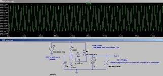
1. Add chokes to improve filtering, or supply the screens from a FET capacitance multiplier (see attached circuit). I have used this circuit reliably in many guitar amps, and it preserves the sound of the amps, while lowering hum and noise.The circuit can reduce the screen voltage of EL34 amps to 390V, which will improve their reliability immensely, without degrading the sound.
2. replace all electrolytics with Panasonic TSHA or similar quality. Do not use multi-section cans, (Marshall, esp). Mount them close to the stage that they are decoupling, and Wire them in directly, no chassis links.
3. Change rectifiers to UF4007 diodes. Move the rectifiers close to the power transformer. bring the first cap up close to these. Trafo-rectifier-cap wiring for the first cap should be 50mm long, each, max.
The rectifier pulse currents are very large, and long wires here couples these into everything.
4. Connect chassis to HT 0V at one place only, near the input jack.
** unless you are certain of your competence, have the safety earth tested professionally**
5. The terrible wiring is often still bad enough for some remanent hum, but you'll need to build from scratch to really overcome this problem!
1. HT power supply filtering is designed for rapid collapse (for sustain, and general sonic mayhem). Usually, the anode supply (wire to the OT) is only filtered by one small capacitor, and does not even include a choke. Some others have a choke, but it only filters the screens of the endstage (VG2) and the preamp. The HT ripple can be tens of volts at the anode. Some amps don't even have a choke at all.
2. Low quality electrolytic capacitors are used in an environment where they get hot. They degrade very quickly, and replacing them after 5 years is not overdoing it. I have attended to a 2004 Fender (in 2009) where the poor-quality Illinois TCC had failed badly enough to make the amp squeal full-time.
3. terrible wiring layout. This is fairly universal, but some 1970s Fenders are unbelievably bad. The placing of all the power supply capacitors in a remote box/position, and running long wires to the preamp is often adopted, with results as bad as can be predicted.
4. Use of chassis for power supply "ground" returns. Marshall especially guilty. This forces the preamp power supply currents to be mixed with power tube currents, and rectifier pulses, to a far worse extent than necessary.
Fixes?
0. Don't add huge amounts of capacitance, or the amp will not sound as it was intended.
1. Add chokes to improve filtering, or supply the screens from a FET capacitance multiplier (see attached circuit). I have used this circuit reliably in many guitar amps, and it preserves the sound of the amps, while lowering hum and noise.The circuit can reduce the screen voltage of EL34 amps to 390V, which will improve their reliability immensely, without degrading the sound.
2. replace all electrolytics with Panasonic TSHA or similar quality. Do not use multi-section cans, (Marshall, esp). Mount them close to the stage that they are decoupling, and Wire them in directly, no chassis links.
3. Change rectifiers to UF4007 diodes. Move the rectifiers close to the power transformer. bring the first cap up close to these. Trafo-rectifier-cap wiring for the first cap should be 50mm long, each, max.
The rectifier pulse currents are very large, and long wires here couples these into everything.
4. Connect chassis to HT 0V at one place only, near the input jack.
** unless you are certain of your competence, have the safety earth tested professionally**
5. The terrible wiring is often still bad enough for some remanent hum, but you'll need to build from scratch to really overcome this problem!
Attachments
With heaters on guitar amps, the high gain means that the first stage can have some sensitivity to heater hum. this is the reason that some Marshalls have a much higher value of cathode bypass cap - 330 - 470uF instead of the usual 22uF.
whether it hums depends on the ECC83/12AX7 in place. Some 1970s, or cheap modern types hum fairly badly. The 12AX7EH (electroHarmonix) is a good-sounding guitar choice, or for even lower hum, the 12AX7LPS. this is usually good enough, but the large bypass cap on V1 cathode, and/or dc on the first stage heater may quiet it further - Provided the implementation is good enough.
DC heaters increase the burden on the mains transformer, and the cap recharge pulses can transmit all over the amp, unless it is well implemented, so this change is only for a last resort.
Surely you would want a smaller cap, as the cathode bypass increases gain over the frequencies it passes.With heaters on guitar amps, the high gain means that the first stage can have some sensitivity to heater hum. this is the reason that some Marshalls have a much higher value of cathode bypass cap - 330 - 470uF instead of the usual 22uF.
The heaters are capacitively coupling 50/60Hz to the cathode. This is not the same as an anode signal - where current flows from anode to cathode.
The cap can help by diverting the noise current to 0V. Otherwise the noise current flows in the cathode resistor, where is DOES mix with the cathode current, & generates hum.
The cap can help by diverting the noise current to 0V. Otherwise the noise current flows in the cathode resistor, where is DOES mix with the cathode current, & generates hum.
The heaters are capacitively coupling 50/60Hz to the cathode. This is not the same as an anode signal - where current flows from anode to cathode.
The cap can help by diverting the noise current to 0V. Otherwise the noise current flows in the cathode resistor, where is DOES mix with the cathode current, & generates hum.
Dual function cathode caps. I like it.
The first stages are in an old low-noise 7025 with lower gain. It was noisy when bumped, but cleaning up the socket and pins seemed to work. The next stage is also supposed to be a 7025, but they're hard to get, so it's a 12AX7.
Rod, thanks for the list, it's all things I would consider but might mis-prioritize. The stock bridge has a small disc cap directly across each of the four diodes, obviously an attempt to suppress switching noise.
This amp is an ultralinear with 6 6L6GC, and I use it only for a big/clean bright guitar, big/clean baritone guitar, or big/clean bass guitar (but not quite SVT big). The output section doesn't have a great breakup mode, and I'm not going for any compression, sag, or sustain with this one...I have other amps for that. So unless I install a switch on the screens, the ultralinear output section doesn't have a great breakup or compression mode anyway; its strength and unique sound is its dynamic range and clean bright punch. So there's really nothing to destroy by adding caps to this one.
This Fender has no power supply chokes. Yet. Fender usually only uses small chokes farther down the ladder.
I have a 10Henry 300ma Edcor, their biggest closed bell-end standard choke, with 72 ohms DC resistance. But at 500+ volts it won't handle quite enough current, so to run everything thru it at 500+ volts, I would need to bypass it with a resistor. That actually might work, and dampen any resonance from the big coil. Then a cap. Then I could add 1 or 2 smaller chokes farther down the network. The correct ideal really big choke would work well in this amp because there's already dropping resistors before the wire to the output trans center tap, so I can add a choke right at the main filters without affecting the output voltage, by just adjusting the values of the existing resistors to achieve the same original voltages out. I was really hoping to use it in a different 50-watt amp.
Then I also have a medium-size (physically smaller, still a closed bell-end type) 88mHY choke with less than 1/100 the inductance value, but which can handle 5 amps and only has 1 ohm DC resistance. It's probably really more appropriate for a power supply for a solid-state amp, but it can handle the high voltage, and it only has 1 ohm DC resistance. At 500+ volts, that means it can handle like 2500 watts. But will 88mH do anything? So the Edcor is overwound with too-thin wire and this one is underwound with too-thick wire.
I was inclined to cut holes in the existing capacitor can and bolt on some capacitor clamps, and put in some bolt-terminal cans. Not dual-section, but bigger cans instead of the standard axial-lead caps.
Is that the Studio Bass 180W (Rivera-era Amp with UL 6x 6L6)? I converted one of these from UL to pentode mode, in part to solve the noise and hum problem. With UL, the Beam Tube's advantage of being able to create a low noise endstage is very difficult to realise.
If you add more capacitance, please check with PSUD2 that the rms current from the mains transformer is not substantially increased, or the clean power will actually be reduced, and the trafo & rectifier overstressed.
The long wiring from the transformer via the rectifier to the cap box is so extreme on those Fender models that a quiet outcome will be very tough. Increasing the C value will raise the peak pulse current, and make it worse.
I used series-connected 220uF 400V TSHA caps in mine, and mounted them right next to the transformer, on some tag-strip.
88mH will not help, sadly. Values in the Henry range are required.
Geeez..
DC heaters Work Fine. Countless examples exist.
Why? the 'if Granpa didn't do it' attitudes?
One can implement snubbers to tame AC heater hum.
But a simple standalone DC heater supply can give a silence that can be strikingly odd to diehard tubies.
Although only IF your design circuit isn't otherwise poor")
DC heaters Work Fine. Countless examples exist.
Why? the 'if Granpa didn't do it' attitudes?
One can implement snubbers to tame AC heater hum.
But a simple standalone DC heater supply can give a silence that can be strikingly odd to diehard tubies.
Although only IF your design circuit isn't otherwise poor
Rod, the Studio Bass, Super Twin, and Super Twin with Reverb are all very similar except the obvious (like reverb, or the super twin not-so-super distortion knob). Except the Studio Bass uses a lower B++ (they all use the same 500V B+ for 6 6L6GC) and different caps in the rotary graphic EQ.
What's PSUD2, simulation software? Wouldn't those have to be some pretty leaky caps to draw more current (except momentarily at start-up of course). If they made that much difference that would kind of prove how badly they were needed.
So some caps right at the rectifier; more right at the load.
What's PSUD2, simulation software? Wouldn't those have to be some pretty leaky caps to draw more current (except momentarily at start-up of course). If they made that much difference that would kind of prove how badly they were needed.
So some caps right at the rectifier; more right at the load.
So give me a very general estimate for sizing the "current spec" for a choke that I run everything thru, including B+, for a big tube guitar amp. (I realize the choke might be enormous, or else it would drop B+ or have too little inductance to be useful, making a retrofit more complicated) I have never even measured the wall draw, so I'm just guessing at the inefficiency, based on the amount of heat but I have less feel for how a tube amp averages over time or momentarily with regards to signal. For a tube amp with 180 watt output, I conjecture it might occasionally want to draw roughly 300 watts from the power transformer secondary; at 500 volts that would be .6 amps = 600 ma I would want a choke to handle. Am I in the ballpark, and how does this conjecture relate to reality?
Of course I realize I need to simuate or measure and do the math as some point...or I'm a hack having fun (a definite possibility).
Of course I realize I need to simuate or measure and do the math as some point...or I'm a hack having fun (a definite possibility).
- Status
- This old topic is closed. If you want to reopen this topic, contact a moderator using the "Report Post" button.
- Home
- Amplifiers
- Tubes / Valves
- What is the ideal low-noise heater power for high-power output tubes?