1. Gost22 wants to regulate current. Placing a CCS in the plate circuit is for a different purpose. The load line would be almost horizontal. Perhaps something to look at. (If you can get a very low capacitance CCS)
2. Yes, you are correct in that a CCS without a bypass cap will get zero gain to the plate.
Gost22, you do need to put a bypass cap in the cathode cct. (parallel with the CCS)
3. The CCS I have suggested will go down to almost 1V...Well within what Gost22 asked for.
4. The bias point is specified at 7.5mA not 2V. Depending on the tube it might be 1.9V or 2.1V but the CCS will compensate for that. LED would not. LED's also have temperature characteristics that are rather bad for a voltage reference.
How about the LM337 ?
look at something like this
Cheers ,
Rens

All the above suggestions are valid.
But IMHO the difficulty lies in that the voltage headroom is only 1.9V.
And we still want the current to remain constant to any small changes in that headroom voltage.
If one will go the the extra complication of a separate supply, either a positive one for the opamp solution,
or a negative one for similar solutions to tube cad, then the problem becomes much simpler to solve.
But if we only want to insert one module between the cathode and Gnd,
then the heavily degenerated JFET is one of the few solutions I know.
Patrick
Take a look at SY's "His Master's Voice" article for a good example of the cascode CCS I am thinking of: http://www.diyaudio.com/forums/diya...oise-thoroughly-modern-tube-phono-preamp.html
Thanks for that recommendation. Not only did it answer my stated concerns, it addressed a few other issues that that I was pondering. Well written too.
But IMHO the difficulty lies in that the voltage headroom is only 1.9V.
Only if one insists on using a CCS in the cathode, instead of (the better approach) using it in the plate.
Maybe this is hopelessly simplistic, but wouldn't a gate-grounded common JFET in series with the cathode ... and a suitably sized source-to-ground resistor (to get the 7.5 ma) be the ticket? I mean... its trivial, it scales really well... and if a J201, J301 or J211 JFET is used ... the minimum voltage drop is very low.
Take a look at SY's "His Master's Voice" article for a good example of the cascode CCS I am thinking of: http://www.diyaudio.com/forums/diya...oise-thoroughly-modern-tube-phono-preamp.html
A+
CCS on the ANODE and LED on the CATHODE.
Build a test board (i.e. with a battery and resistor...) to set each CCS circuit mA's and away you go....
A+
CCS on the ANODE and LED on the CATHODE.
Build a test board (i.e. with a battery and resistor...) to set each CCS circuit mA's and away you go....
Yes, and if want stable working point add servo to anode load turning such a way CCS into gyrator.
Please be more specific your offer for circuit or schematic to solve the problem.
thank you!
Which problem: to make an amp that works like non-linear attenuator?
Please be more specific your offer for circuit or schematic to solve the problem.
thank you!
As Kevinkr noted.
http://www.diyaudio.com/forums/diya...oise-thoroughly-modern-tube-phono-preamp.html
This is a good thread to start with.
Hi all!
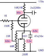
How about something like this for source constant current at the cathode?
Or you can offer something better.
thank you!

I'm not a tube guy, but it seems to me that with a CCS in the cathode, there will be no signal current through the tube and hence no output signal on the plate.
Is that what is wanted??
jan
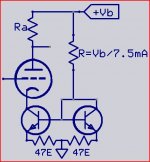
Simple R:2R divider does the trick.
This solves the problem - while maintaining the elegance of a constant-current device, allowing the cathode to take on whatever value (voltage bias) necessary for the tube's nominal operation. A couple of resistors in a voltage-divider orientation and a low bias-point JFET get the job done, for maybe less than a dollar.
This solves the problem - while maintaining the elegance of a constant-current device, allowing the cathode to take on whatever value (voltage bias) necessary for the tube's nominal operation. A couple of resistors in a voltage-divider orientation and a low bias-point JFET get the job done, for maybe less than a dollar.
Attachments
")
How about like this
Mona
That one's perfectly workable as well ... with the exception that it needs the cathode-side NPN bypassed to become a constant-current constant voltage power supply as well (in DC), and a variable current, constant voltage supply in the A/C domain.
GoatGuy
Hi all!
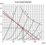
What is a better solution (see graph)
I go with the anode resistor Ra=10k (+B=170V) and cathodic current of 7.6mA and the anode resistor Ra=8K2 (+B=150V) and cathodic current of 7mA.
What is the better of these two solutions for cathodic current of 7.6mA.
What do I get with this solution is better than GoatGuy or Ketje, or go with the cathode resistor Rk=263R for Ik=7.6mA (Rk=286R for Ik=7mA)?
Thank you for your cooperation.
Cheers!
Attachments
Last edited:
Hi all!
What is a better solution (see graph)
I go with the anode resistor Ra=10k (+B=170V) and cathodic current of 7.6mA and the anode resistor Ra=8K2 (+B=150V) and cathodic current of 7mA.
What is the better of these two solutions for cathodic current of 7.6mA.
What do I get with this solution is better than GoatGuy or Ketje, or go with the cathode resistor Rk=263R for Ik=7.6mA (Rk=286R for Ik=7mA)?
Thank you for your cooperation.
Cheers!
Hmmm... i think your trying to ask "which is better", without having a sense of "what I am trying to accomplish" with the amplifier stage!
Its REAL simple... if you are trying to INCREASE gain, you use higher resistor values, and higher voltages in the power supply. It has long been forgotten, but the "reason" we use the values that are common-and-popular ... is because in the old days, resistors were expensive, wickedly so ... and therefore within the limits of power dissipation and safe circuit operation (all the capacitors blow if too high voltages are used, and the tube "fades to death", or has its heater fail) ... so its all a compromise.
The DESIGN POINT (typically, though not always) for a non-output amplification stage is this: the plate voltage should be far enough below the supply voltage so that the very widest voltage-swings expected ("designed for") the input, on amplification, result in a clean full-range waveform on the output. Unless you're designing (intentionally) a fuzz box or guitar-amplifier 'coloration stage', then for HiFi audio, lower amplification, more linear operation, closer to the "midpoint" of the V+ supply ... applies.
V+ = 150 and Rplate = 8.2 kohms will not be significantly different (except for gain) over V+ = 170V and Rplate = 10K ... -0.81 db, when you take the effect on mu and operating point into effect.
GoatGuy
- Status
- This old topic is closed. If you want to reopen this topic, contact a moderator using the "Report Post" button.
- Home
- Amplifiers
- Tubes / Valves
- Circuit or schematic for current source of 7.5mA