Hi everyone.
Have started up a project of renovating and modifying an old tube amplifier.
Here you can find the schematics for the amplifier.
http://www.jogis-roehrenbude.de/Oldies/Sennheiser_VKS-203/Sennheiser-S-Unkomp.jpg
In general my goal is to get a better sounding (ofc") ) amplifier.
) amplifier.
1. I have replaced all capacitors, is there any gain by replacing the resistors as well, and what type of resistors should I use?
2. I'm planning to move the power supply out of the amplifier to get rid of the "hum", should I switch to diods instead of the rectifier-tube?
2.1. In the manual for the rectifier tube (EZ81/6CA4) it states that the reservoir electrolytic capacitors should maximum be 50 uF, but I have read in many sources that, you should use as large capacitors for the power supply that you can find.
2.2. From the transformator there is a 20 V line, and to that line there is one diod (Gl 1), what is the purpose for that diod?
2.3 Should I ad a pi filter to the power supply or is it useless cause it's an class A amp?
Is there any other modifications to get a better sound that you can recommend?
Have started up a project of renovating and modifying an old tube amplifier.
Here you can find the schematics for the amplifier.
http://www.jogis-roehrenbude.de/Oldies/Sennheiser_VKS-203/Sennheiser-S-Unkomp.jpg
In general my goal is to get a better sounding (ofc
) amplifier.1. I have replaced all capacitors, is there any gain by replacing the resistors as well, and what type of resistors should I use?
2. I'm planning to move the power supply out of the amplifier to get rid of the "hum", should I switch to diods instead of the rectifier-tube?
2.1. In the manual for the rectifier tube (EZ81/6CA4) it states that the reservoir electrolytic capacitors should maximum be 50 uF, but I have read in many sources that, you should use as large capacitors for the power supply that you can find.
2.2. From the transformator there is a 20 V line, and to that line there is one diod (Gl 1), what is the purpose for that diod?
2.3 Should I ad a pi filter to the power supply or is it useless cause it's an class A amp?
Is there any other modifications to get a better sound that you can recommend?
Arbitrarily replacing resistors will often yield minimal improvements. Replace only those that are far off value or otherwise defective or known to be noisy.1. I have replaced all capacitors, is there any gain by replacing the resistors as well, and what type of resistors should I use?
Slightly difficult to give a definitive answer in this case. Removing the power supply may not help your hum unless you know the transformer is actually radiating hum. Better filtering should be tried first because it clearly needs it. Tubes and/or improper grounding or wiring can also produce hum. More below.2. I'm planning to move the power supply out of the amplifier to get rid of the "hum", should I switch to diods instead of the rectifier-tube?
The first capacitor size restriction is there to protect the tube from overcurrent during start up. However, if the capacitor and tube are in good shape, with no leakage in the cap, a larger value can be used. I do it, but that's with good old American NOS tubes. I would not risk it with todays tubes.2.1. In the manual for the rectifier tube (EZ81/6CA4) it states that the reservoir electrolytic capacitors should maximum be 50 uF, but I have read in many sources that, you should use as large capacitors for the power supply that you can find.
That voltage is the bias source for the output tubes. They are run with fixed bias and that diode and negative voltage is necessary. You must keep it.2.2. From the transformator there is a 20 V line, and to that line there is one diod (Gl 1), what is the purpose for that diod?
The small tubes run class A, but the output tubes are class AB1. Now, as I mentioned above, the filtering is very minimal and converting to a pi filtering scheme is a good idea. Either a small choke or a low value resistor followed by a large filter capacitor should help your hum. Also, if you went to SS diodes you could gain a little more voltage to help make up for the loss through a choke or resistor. And you could safely increase the first capacitor value as well. Less say 100uf or more for the first one and several hundred uf for the second capacitor. Lots of people on this forum recommend Schottky diodes because they are lower noise. Maybe so, but I've never been actually able to "hear" the difference. But it doesn't hurt to use them and is good practice nowadays because they're cheap enough.2.3 Should I ad a pi filter to the power supply or is it useless cause it's an class A amp?
The only modification I would make is to add small (1 ohm) resistors in the output tube's cathode to ground to measure quiescent current across to insure good balance.
Why do you want those switches?
Some prefer the sound of triode and/or without NF, different music also could be accommodated with different modes of operation.
Jaz
Some prefer the sound of triode and/or without NF, different music also could be accommodated with different modes of operation.
Jaz
If the amp really needs NFB, youi'll never want to listen to it without feedback. And if it's good and linear enough to enjoy it without NFB, why would you ever want to apply some?
My suggestions were to try these simple mods before you actually punch holes and install them in the amp... The FB switch defeats (as in remove) the existing FB - not to add more FB to what is already there. Many amps "designed" with FB sound better without it. Since you are already replacing all caps in the amp, what's a few more switches if they can give you more options at your disposal?
Jaz
Since you are already replacing all caps in the amp, what's a few more switches if they can give you more options at your disposal? Jaz
Don't mess up with feedback. Without feedback you will get higher gain, more hum, more distortions, worse frequency response, and worse control of speakers. This amp needs it. It is class AB amp with ultralinear output. Fedback-less amps have to be designed especially in order to sound well. You can't turn a tractor into a sport car and vice verse by flipping a switch, it is physically impossible, even when some tractors have such switches on their front panels.
You can replace tube rectifier by couple of SS diodes, and drop excess voltage on MOSFET - based filter consisting of resistive voltage divider shunted by capacitor, and MOSFET follower. Such a way you will get rid of hum without moving out power supply that would introduce new problems.
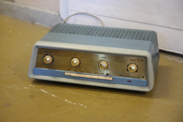
Edit: I found some picture. Does it look similar?
It is Bulgarian Mono25-2 amp for PA applications. 2xEL34 output.

You can replace tube rectifier by couple of SS diodes, and drop excess voltage on MOSFET - based filter consisting of resistive voltage divider shunted by capacitor, and MOSFET follower. Such a way you will get rid of hum without moving out power supply that would introduce new problems.
Edit: I found some picture. Does it look similar?
It is Bulgarian Mono25-2 amp for PA applications. 2xEL34 output.
An externally hosted image should be here but it was not working when we last tested it.
Last edited:
You can replace tube rectifier by couple of SS diodes, and drop excess voltage on MOSFET - based filter consisting of resistive voltage divider shunted by capacitor, and MOSFET follower. Such a way you will get rid of hum without moving out power supply that would introduce new problems.
Are waiting on a delivery of bigger caps (820 uf), so can't I use resistors
instead of a mosfet to bring down the voltage??
something similar to this
http://diyaudioprojects.com/Tubes/6T9-Tube-Amp-Kit/6T9-Valve-Power-Supply-Schematic.png
Are waiting on a delivery of bigger caps (820 uf), so can't I use resistors
instead of a mosfet to bring down the voltage??
something similar to this
http://diyaudioprojects.com/Tubes/6T9-Tube-Amp-Kit/6T9-Valve-Power-Supply-Schematic.png
It is not the same. Your amp works in class AB and consumes current that depends on loudness. That means, voltage after resistor will depend a lot on loudness.
Mosfet does no bring down voltage, it supplies the amp by filtered voltage. However, in order to work it needs some voltage, and as the result it brings it down as well.
Source follower has low output resistance, so the voltage will depend on current much less than without it. You get no hum and more stable amp that behaves better on transients.
- Status
- This old topic is closed. If you want to reopen this topic, contact a moderator using the "Report Post" button.
- Home
- Amplifiers
- Tubes / Valves
- Modifications to Sennheiser VKS 203