Tom,
I have some Power and Output trannies sitting on the shelf for a couple of 300B monoblocks. One of those "I'll get round to" projects that I never have - so this looks good. Also have a pair of JJ 300Bs and some ECC99.
A few questions:
1) Vcascode - I take it that this is set at around say 30V less than +400V rail to limit the voltage across the LT3092 to less than its max 40V rating. Is that correct?
2) I haven't seen that MOSFET + CCS Chip style CCS before. Have you tried anything simpler for the CCS load (A Buddha CCS or something similar). I have no experience with CCS as anode loads but have used them a lot as diff amp tails and have never managed to get any better performance than a cascode bipolar transistor arrangement. Past a point device/lead capacitance becomes the limiting factor (at the high frequency end).
Thanks,
Ian
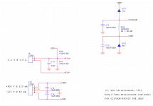
I've attached the "supply" portion of the schematic. This amp is fed from a +400 V regulated supply (I use my 21st Century Maida for this). The -225 V is generated by a string of zeners with a MOS follower.
Sounds like a good start for a project...")
That's exactly right. I use Vcascode = 15 V less than B+, but you could use 30 V as well. You'd have less headroom for the input valve, but that's mostly of academic value. The circuit has more than 100 V of headroom. An extra 15 V isn't going to make much difference.
It's a standard IC-based CCS with a MOS cascode. There's nothing mythical about it. It just works... And it's actually pretty simple. R1, R2 set the current. The LT3092 provides a current that is very stable with temperature. In addition, it's a quite low noise current source. C2 further rolls off the noise, and C1 provides HF compensation to improve the transient response. Q2 is there to keep the voltage across the IC to a reasonable level - it also dissipates all the power in that circuit. Heatsink needed!
I looked at a handful of CCSes before I settled on the LT3092. But most discrete CCSes are very temperature dependent and I don't like the idea of bias points shifting around as the amp heats up. I designed a couple of temperature compensated current sources, but they were all of higher complexity than the IC + a few passives and still required a cascode to survive the voltage. So I went "simple is good" and let Linear Technology worry about the temperature compensation...
I did try the IXYS 10M45 CCS. That'll work too, but I like the sound of the LT+cascode much better. I speculate that the improvement in sound is because the output impedance of the cascoded CCS is much higher (orders of magnitude) than that of the 10M45.
I'm not familiar with the two circuits you mention. If you have a schematic, I'd be interested. I'm curious...
BTW, I intend to get some PCBs made professionally for this project. I'll be selling the excess boards from my website. I'm hoping to get the project done before Christmas, but would prefer to not make too many promises regarding availability date. Just letting you know it's in the pipe...
~Tom
Tom,
I have some Power and Output trannies sitting on the shelf for a couple of 300B monoblocks. One of those "I'll get round to" projects that I never have - so this looks good. Also have a pair of JJ 300Bs and some ECC99.
Sounds like a good start for a project...
1) Vcascode - I take it that this is set at around say 30V less than +400V rail to limit the voltage across the LT3092 to less than its max 40V rating. Is that correct?
That's exactly right. I use Vcascode = 15 V less than B+, but you could use 30 V as well. You'd have less headroom for the input valve, but that's mostly of academic value. The circuit has more than 100 V of headroom. An extra 15 V isn't going to make much difference.
2) I haven't seen that MOSFET + CCS Chip style CCS before. Have you tried anything simpler for the CCS load
It's a standard IC-based CCS with a MOS cascode. There's nothing mythical about it. It just works...
And it's actually pretty simple. R1, R2 set the current. The LT3092 provides a current that is very stable with temperature. In addition, it's a quite low noise current source. C2 further rolls off the noise, and C1 provides HF compensation to improve the transient response. Q2 is there to keep the voltage across the IC to a reasonable level - it also dissipates all the power in that circuit. Heatsink needed!I looked at a handful of CCSes before I settled on the LT3092. But most discrete CCSes are very temperature dependent and I don't like the idea of bias points shifting around as the amp heats up. I designed a couple of temperature compensated current sources, but they were all of higher complexity than the IC + a few passives and still required a cascode to survive the voltage. So I went "simple is good" and let Linear Technology worry about the temperature compensation...
I did try the IXYS 10M45 CCS. That'll work too, but I like the sound of the LT+cascode much better. I speculate that the improvement in sound is because the output impedance of the cascoded CCS is much higher (orders of magnitude) than that of the 10M45.
I'm not familiar with the two circuits you mention. If you have a schematic, I'd be interested. I'm curious...
BTW, I intend to get some PCBs made professionally for this project. I'll be selling the excess boards from my website. I'm hoping to get the project done before Christmas, but would prefer to not make too many promises regarding availability date. Just letting you know it's in the pipe...
~Tom
Attachments
Last edited:
With Vak = 180 V, there isn't enough head room on a 225 V supply to run the input stage. Of course, one could run the CCS from the B+ and put the cathode of the input tube at -225 V. This would dissipate rather large amounts of power in the cascode MOSFET. That's probably manageable if the MOS can sit on an external heat sink.
However, with such an arrangement, the bias of the output tube is now dependent on the characteristics of two tubes. And the Vak varies a lot more than Vgk both as the tube warms up and from tube to tube, so controlling the bias on the output tube will be a challenge.
There is (at least) one solution to this. I tried using a 70 H inductor/choke load on the input tube. If one end of the choke is grounded and the other connected to the anode of the input tube with the rest of the amp DC coupled from there, it actually provides nice control of the output tube bias. One can use cathode bias on the 300B pretty easily. I really like the simplicity of that circuit. A couple of "light bulbs" some resistors, and an inductor. BAM! You have an amp. I built one, actually. It was inspired by Jack Elliano's 300B DRD but rigged as I describe above.
I ended up going back to the circuit I posted yesterday for a couple of reasons: The THD on the input tube is heavily dependent on the bias point of the tube (DUH!) But to control the bias point when the anode is grounded through an inductor, a variable supply is needed. This isn't hard to do, but it adds complexity and with the tube I used at the time (d3A, I think) there's enough tube-to-tube variation that the supply would have to be customized to each tube. In addition, the lowest THD I could get with that circuit was on the order of 0.5 % and it was rather frequency dependent. I'd have to check my notes if you want more data. I auditioned a few different biasing options for the 300B and liked fixed bias the best. So my conclusion was that with a DC coupled amp, I would trade off amp complexity in exchange for supply complexity and get worse performance that I get with my current circuit.
I'm not a fan of capacitors in the signal path either. But I find that a quality polypropylene cap is transparent if used properly. By using a cathode or source follower, one avoids the issues with blocking distortion as well.
In the 300B DRD circuit, you exchange the cap for an inductor in the signal path instead. Tradeoffs, tradeoffs.
Sorry for the long-winded reply, but I've spent the past two or three years fiddling with this 300B amp, so I have lots of stories to tell...
~Tom
Folks,
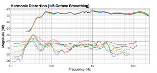
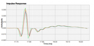
I've tested d3A, ECC99, 6N6P, and 12BH7A as driver tubes in my 300B driver design. Attached are my end-to-end measurements (amplitude, H2, H3, impulse response).
RED = 12BH7A-300B
BLUE = ECC99-300B
YELLOW = 6N6P-300B
GREEN = LME49811-based sand amp for reference.
Measurements of the THD of the amp with resistive load reveal the following:
12BH7A: 0.39 % THD @ 1 W; 4.8 W @ 1 %; 9.7 W @ 2 %; 10.2 W @ 3 % THD.
6N6P: 0.16 % THD @ 1 W; 9.7 W @ 1 %; 11.4 W @ 2 %; 11.8 W @ 3 % THD.
ECC99: 0.18 % THD @ 1 W; 8.9 W @ 1 %; 9.6 W @ 2 %; 9.8 W @ 3 % THD.
The input tubes were biased as follows: 12BH7A: Vgk = -11.2 V; Ia = 12 mA. ECC99: Vgk = -6.0 V; Ia = 12 mA. 6N6P: Vgk = -6.2 V; Ia = 15 mA.
The cathode followers were running at 4.4 mA. For the cathode followers, Vak was roughly: 12BH7A: 230 V; ECC99: 125 V; 6N6P: 170 V. These voltages were chosen for optimal THD.
I'm surprised that the 12BH7A distorts so much. I wouldn't have thought that from looking at the plate curves. I'm guessing it has to do with the source follower. 12BH7A is not a very good candidate for a source follower due to its low gm. And I suspect it isn't entirely happy at the 4.5 mA I'm running through that source follower. I did try upping the current, but that made negligible improvement.
I'm thinking that the 12BH7A is probably better suited for 300B amps with the anode of the input tube (12BH7A) connected directly to the 300B grid (via a cap if necessary) rather than through a cathode follower. Maybe a source follower could improve the THD, but I have decided to not use a source follower as I prefer the sound of a good cathode follower.
Listening tests:
To my ears, on my system, the 12BH7A sounds a lot like the d3A. It's a nice tube. No question about it. It reveals a lot of detail, but to my ears, it's a bit fuzzy in the highs. The lisp on hard consonants is more pronounced. And at higher SPLs I found it kinda straining to listen to.
The ECC99 is nice as well. I don't find it as revealing as the 12BH7A/d3A and perhaps a bit harsh, but for a current production $15 tube, it's pretty damn good! This tube was my favorite until I was led to the 6N6P.
In my opinion, the 6N6P is the best compromise between harshness and precision. My amp likes that tube.
The end result is the same as last time I posted. My board will support 12BH7A, ECC99, and 6N6P by configuring a couple of wire jumpers. One can wire in a pair of d3As in place of an ECC99 if desired.
~Tom
Attachments
Yes. I have news. The past few weeks have involved power supply work and mucking with various rectification schemes. Attached is where I ended up. I tried Schottky diodes, regular diodes, X caps, etc. and wasn't able to measure any significant difference between one type or the other so I went "standard" with the supply.
Tomorrow I hope to get some work done on the amp board. I've been mulling over how to make it work with the chassis layout I have in mind. I think I might make the amp board a long, skinny one. Like 3x5 or 3x6 inch with holes for the 300B sockets.
Don't change that channel! We'll be right back...
~Tom
Attachments
I have a 845 SET that uses a 6AC7 pentode and a 300B as drivers. It's wanting in many ways and so I've been following this thread with great interest. Or perhaps I should say trying to follow...
It's the cathode follower that I'm having trouble following. I retread MJ and Boskie on the subject last night and am still in the dark. There is a big gap in my understanding. Perhaps someone can shed some light.
It's my understanding that the cathode follower will have just under unity gain and will need to swing considerable voltage to drive the big triode. Given the near unity gain, the grid swing can be no less than that across the cathode resistor, no?? Yet the ECC99 Grid voltage lines max out at about -20 volts. So, how is it possible for this ECC99 to swing more than say 10 volts pp?
School me.
Last edited:
For this circuit, the operating point of the cathode follower is set with the bias pot, R13. This sets the voltage at the grid of the cathode follower. The voltage on the anode is set by a source follower in my case, but it could as well have been a constant DC source of roughly 85 V. The load resistor, R10, will cause some current to be drawn through the tube under this condition. The tube will settle at some Vgk determined by the characteristics of the tube. In case of the ECC99, I seem to recall this being around Vgk = 5 V for the conditions noted in the schematic.
In summary, the voltage across the load resistor, R10, determines the current through the cathode follower. Ia = V(R10)/R10. If V(R10) is known, so is Vak of the cathode follower. From this, Vgk can be found on the plate curves.
So that's the DC operating point.
When a signal is applied, the cathode voltage will track the grid voltage. As you say, the gain is slightly less than unity, so a 1 V increase in grid voltage will cause an increase in cathode voltage of approximately 1 V. This in turn increases the anode current as V(R10) is now 1 V higher. You can work out the resulting change in Vgk from the plate curves. You'll find that it swings much less than the 1 V applied.
Hope this clears things up a bit.
~Tom
Last edited:
The gain of my power amp is about 2 V/V (6 dB). So yeah... On the low side. Part of that is by design, actually. Running higher signal levels between the pre and power amp gives you better signal integrity as you aren't attenuating as much in the volume control only to gain it back up in the power amp.
To drive this amp to clipping you'll need a bit over 6 V RMS. So it definitely requires a preamp with some stones. I'm considering following it up with a preamp design, actually.
If you don't need differential input, you can take the input transformer out. I have options for a regular AC coupled input on the board. This will increase the power amp gain to 9 dB, hence, only requiring 4.25 V RMS to get to clipping.
That said, I use speakers that are roughly 90 dB efficient and have no trouble playing music loud. I typically run with the volume control set to -35 dB for background listening, -25 dB for actual listening to the music, and between -10 and 0 dB for loud. I'm driving my preamp with either a CD player - or these days more commonly an Airport Express through a Saffire DAC.
~Tom
Pictures
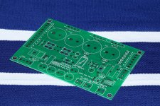
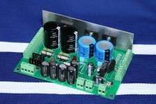
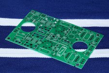
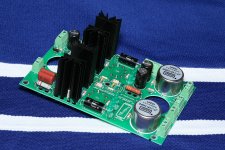
Pictures of the supply board.
The supply board is intended for use with the ClassicTone 40-18069 power transformer available from Triode Electronics.
The board allows for selection of the following mains voltages: 120 V, 230 V, 240 V by moving a couple of wire jumpers. A soft-start circuit ensures that the inrush current is kept under control during start-up.
The output voltages are: 525 V (unregulated) for B+; -220 V (zener regulated) for bias; 2 x 20 V (unregulated) for filaments. In addition, an output for a POWER ON indicator LED is provided.
Now, of course 525 V and 20 V are too high for use directly. However, they're just about perfect for use with my 21st Century Maida Regulator for generating 400 V B+ and my Universal Filament Regulators for generating 6.3 V and 5.0 V. I run the two 5.0 V regulators from one 20 V output and the regulator for the 6.3 V off of its own 20 V output. Works great.
For those who wish to use lower B+ voltages, two wires can be swapped on the transformer secondary, resulting in an unregulated voltage of roughly 450 V. This would be quite suitable for regulated B+ voltages in the 340~380 V range.
The board measures 4.0 x 6.0 inches.
I'll follow up with a schematic and design notes in a bit.
Attachments
Last edited:
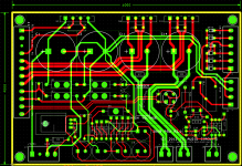
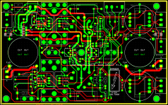
More pictures
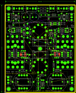
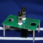
And now for pictures of the amplifier board. Note that the tube sockets are mounted on the back side of the board such that the tubes can poke through the top plate of the chassis. The large cutouts are where the 300B sockets go. The sockets will be mounted to the top plate of the chassis and their pins will poke through the cutouts in the PCB. The pins will be connected by short lengths of wire to holes in the PCB.
In addition to the sockets, I've chosen to mount the bias pots on the back side of the board as well. That way, I'll be able to adjust the bias through a hole in the top plate of the chassis. You can mount the pots on the component side of the board if you prefer adjustment from the bottom of the amp.
All holes for components or screws that will poke through or require access through the top chassis panel are laid out symmetrically. This was actually a bit of a challenge, but I think it'll result in a really nice looking top plate on the chassis.
The 300Bs are 4.5 inches apart. The two driver tubes are two inches apart and centered between the 300Bs. It's a pretty neat and compact layout.
The board allows for use of a Jensen JT-11P-1HPC input transformer. If you would prefer a single-ended input, the board supports the use of an input capacitor instead.
The board has direct support for 6N6P (as pictured), ECC99, and 12BH7A. Switching between tube types require swapping a couple of components and wire links. The board may also be used with d3A tubes, though, this will require some creative wiring to connect two d3A pentodes to a socket that's intended for use with a dual triode. I've done it with good results, though.
The board measures: 4.0 x 6.4 inches. The cutouts for the 300B tube sockets measure 1.15 inches in diameter.
~Tom
Attachments
Last edited:
Boards available for purchase on my website: http://www.neurochrome.com/audio
For a stereo amp, you'll need:
One (1) 300B_PSU_R2p0 300B Supply Board
One (1) 300B_Driver_R1.0 6N6P/ECC99/12BH7A 300B Driver Board
Three (3) FILREG_3P2 Universal Filament Regulator Boards
One (1) MaidaReg_1P0 21st Century Maida Regulator Board
I'll follow up with the remaining design collateral over the next couple of days.
~Tom
Last edited:
- Status
- This old topic is closed. If you want to reopen this topic, contact a moderator using the "Report Post" button.
- Home
- Vendor's Bazaar
- DeathTrap400™ : : A Pretty Damn Good 300B Amp