I looked at that but the 5 amp filament requirement presents a problem for the 3.25 amp transfo windings. That and the socket change are negatives. Price and availability are positives.<snip>
If you turn that 3.25 amp winding into DC you have to de-rate it. 3.25 x .6 = ~2 amps.
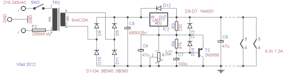
Here is what I did. 77% efficient and not terribly buzzy. The snubber diodes do make it quieter. Also your big filter cap has to be rated for the ripple which is why I suspect your current circuit blew one up. I used a Panasonic TS-UP (8 amp)
I have purchased 6 graphite GM70's from ebay and I would say the build quality is top notch. I've only been running two of them maybe 100 hours so far but the bias setting is rock solid.
Good luck, the chassis on your amp looks awesome!
Attachments
Eeek! I hope you paid pennies on the pound for that broken Chinese amp! <snip>
About a dollar a pound but it's a two man lift
")
And the outboard supply was what got me thinking about the GM70s. If I'm going that far why not go with the 20v triodes?
I did operating it from my bench supply for a while but the bench supply was a loud fan cooled affair so not very practical.
I did make some real progress last night. I was able to isolate the circuit card failure and "rectify" that problem. The pun is that the continuity to chassis ground was in the bridge rectifier traces and by lifting those I have isolated filament supply once again.
I installed a .68R resistor and a 10,000uf cap to drop the voltage a couple of volts to about 10. That got the ripple down to about 80mv. I'm tempted to try an LT 1085 as MelB suggests to lower the ripple further.
And I think you are correct about the HT supply. I replaced some 450 v caps with some higher temp rated 500 v caps. The resistors look to be proper.
MelB: I considered the LT1085 approach and decided on the CRC approach over concern that the inrush from the cold filaments would be too much for the regulator. I will note that the photos I have seen of new versions of this amp appear to have an additional heat sink leading me to conclude that they are now using such a design. That may account for the excessive filament voltage on this unit. And BTW, where are you getting the 20v LT1085? The datasheets I have reviewed spec max out at 15.
Last edited:
He's using an LT1083 which specs out at 7.5A, and is using the adjustable version. I guess the 7.5A LT1083 will start into a 3A filamentary load, the LT1084 (5A) which I am using will not and needs a little help as I mentioned in a previous post. There is a pretty big difference in cost between the LT1083/84/85 which is why I am using the 5A version as opposed to the 7.5A version.
The LT1085 is too small unless you bypass a significant amount of current (say 1A - 1.5A) around it which is viable IMO as it will also allow it to start into what looks pretty much like a short circuit to it.
The LT1085 is too small unless you bypass a significant amount of current (say 1A - 1.5A) around it which is viable IMO as it will also allow it to start into what looks pretty much like a short circuit to it.
OK, we posted on top of one another. I found the Linear datasheet for the 1083. That's a handy device. Thanks
I'm tempted to hang with the CRC arrangement for a while. It lends itself to a tidy retrofit and there is really not that much room under the hood. Unfortunately, I won't be able to listen to this until I order up some 845s. (I was using the previous owners tubes and no longer have them). Do you think the filament supply with the 80 mv ripple will be low enough to give a satisfactory result? I think I measured over 150mv previously and I thought that created excessive hum. I can recall reading somewhere a max ripple design recommendation and I vaguely recall that being 150mv.
I'm tempted to hang with the CRC arrangement for a while. It lends itself to a tidy retrofit and there is really not that much room under the hood. Unfortunately, I won't be able to listen to this until I order up some 845s. (I was using the previous owners tubes and no longer have them). Do you think the filament supply with the 80 mv ripple will be low enough to give a satisfactory result? I think I measured over 150mv previously and I thought that created excessive hum. I can recall reading somewhere a max ripple design recommendation and I vaguely recall that being 150mv.
Last edited:
Sorry above when I was talking about buzzy I meant the transformer hummm. My GM70 has < 0.004 mV on the speaker terminals with the speakers attached. The first version I made I used an older Hammond 272JX which had a fairly loud transformer humm. The newer Hammonds (300 version)are much quieter as is the 167P18.
Do you have room to bump up the size of the caps and maybe swap that resistor for an inductor? (If you have hummm that is.) If there was acceptable humm I would go with what you have.
Do you have room to bump up the size of the caps and maybe swap that resistor for an inductor? (If you have hummm that is.) If there was acceptable humm I would go with what you have.
As it is now I have 4 x 10,000 uf before the resistor on the circuit board and then a single 10,000 uf after. It would be nice if I could reverse that CRC, no? Another cap lowers the ripple only about 15% and it would be a struggle to find a location for it. I don't happen to have any values besides the 10K at the moment. It's all finished now and I just need to get some triodes and give it a listen. I'll post the results.
Here is what I did.
Hi.
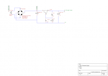
You could add a soft start to that regulator, the filament would really appreciate it...
Like in this (lower power) schematic:
Attachments
I think it starts fairly slowly already(?) Max short circuit current from the LT1083 data sheet is ~9 amps. I measure the GM70 cold filament at 0.66 ohms. So even IF the 47,000 uF cap was fully charged and I flipped the switch it would "only" get 0.66 x 9 = ~6 volts across the filament and it's a damn big filament. If you look at my schematic above I have 47uF on the adjustment pin. If I go any larger it won't start the GM70. It just sits there and says No Thank You. I don't know if it would like the soft start circuit(?)
I guess if the LT1083 was not current limited slow start might be advisable as it could be hit with ~30 amps with no limiting.
Or perhaps I'm abusing my GM70's.....
I guess if the LT1083 was not current limited slow start might be advisable as it could be hit with ~30 amps with no limiting.
Or perhaps I'm abusing my GM70's.....
I had the same problem with the current limiting in the LT1084 in my GM70 amplifier. I found two ways to resolve it - one was to place a 10 ohm NTC thermistor in series with the supply to the regulator, the other which I ultimately preferred was to bypass roughly 1A around the regulator using a resistor in parallel with the regulator. Make sure the resistor can handle the dissipation in the event the regulator doesn't start for some reason.
The problem with the NTC is that it won't current limit in the event of a line transient event while it is hot which would cause the regulator to latch off.
These regulators do not like to start into filamentary loads with large inrush currents. Something else you could try is a circuit to deliberately limit the filament current to just a little over 3A which the regulator will probably be happy with.
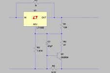
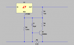
Edit: I've uploaded a couple of different circuits I have used in other applications.. I've not used these circuits specifically with the GM70 since I use Rod Coleman's CCS, but they both provide current limiting in the region of 4 - 5A and one variant shows the parallel resistor that I do use with my regulators. (Given the very low output impedance and high loop feedback in these regulators the resistor degrades the ripple rejection only very slightly if at all.)
One other comment I would make is that for best performance (ripply rejection) these regulators really like to see a minimum of about 3V across them, and this obviously should be the case at 10% low line - so something like 25V under nominal line is advisable. (Yes lots of heat) I would replace the bridge rectifier with discrete Schottky diodes (or a bridge if reasonably priced) to get another volt or so out of the supply assuming a conventional silicon bridge rectifier.
The problem with the NTC is that it won't current limit in the event of a line transient event while it is hot which would cause the regulator to latch off.
These regulators do not like to start into filamentary loads with large inrush currents. Something else you could try is a circuit to deliberately limit the filament current to just a little over 3A which the regulator will probably be happy with.
Edit: I've uploaded a couple of different circuits I have used in other applications.. I've not used these circuits specifically with the GM70 since I use Rod Coleman's CCS, but they both provide current limiting in the region of 4 - 5A and one variant shows the parallel resistor that I do use with my regulators. (Given the very low output impedance and high loop feedback in these regulators the resistor degrades the ripple rejection only very slightly if at all.)
One other comment I would make is that for best performance (ripply rejection) these regulators really like to see a minimum of about 3V across them, and this obviously should be the case at 10% low line - so something like 25V under nominal line is advisable. (Yes lots of heat) I would replace the bridge rectifier with discrete Schottky diodes (or a bridge if reasonably priced) to get another volt or so out of the supply assuming a conventional silicon bridge rectifier.
Attachments
Thanks for the input!
I did start with just a cheap 50 amp bridge rectifier, then after a bunch of reading here I searched for a diode with less switching noise and came up with these:
http://www.microsemi.com/en/sites/default/files/datasheets/APT30D20BCT(G)_B.pdf
There seems to be much less noise from the transformer for sure! Can I perceive any improvement in sound? I'll give it a strong maybe. They are giving me about the same voltage drop as the cheapo bridge did. The regulation seems to be really good even with only ~ 2- 2.5v of drop. If I put my pretty good volt meter on the filament on the mV setting it drops to 0.125mV or less.
However in the spirit of DIY (I will try anything) I have ordered some of these:
http://www.vishay.com/docs/94137/94137.pdf
Being far from an expert in diode switching noise. How do these stack up to the ones I currently have in my amps and if they have more switching noise what is the trade off between noise and improved regulation? Or better yet does anyone have a favorite "low noise" diode?
The Vishay schottkys will give much less in the way of reverse-recovery pulses compared to ordinary PN bridges. If you want to ride first class, avoid over-rating the diodes too much. In a GM70 supply, with bridge 5 ..10A 45V parts will be plenty comfortable - and the lower the current rating, the lower the expected capacitance, usually. This helps to keep out any rectifier turn-OFF voltage spikes, driven by the transformer's secondary inductance. You can tame these spikes quite well with a snubber across the secondary - 47R + 47nF series connected. The 47R carbon composition, the 47nF an FKP (1000V LCR PC/HV/S) or stacked MKP (Panasonic 250V).
Nothing can help the problems caused by the LT108x itself though - such as the way it will try to regulate-out the music signal which naturally develops across the ends of the filament. Or the Electrolytic across the filament shunting the same signal (frequency-dependent, unless you use about 47000uF or more), or the high noise level.
Nothing can help the problems caused by the LT108x itself though - such as the way it will try to regulate-out the music signal which naturally develops across the ends of the filament. Or the Electrolytic across the filament shunting the same signal (frequency-dependent, unless you use about 47000uF or more), or the high noise level.
I got some 845s in and gave it a listen. It was horrible. The wave form off the pentode is the first problem.
Here is a LINK to a curve of the 6(zh)4 pentode. I can't even draw the OP with the 470 Rk provided. I just can't figure that out, am I missing something?
The manufacturer used a 100K plate load resistor, a 470R cathode resistor and a 470K screen resistor. I breadboarded the circuit and tried some different values. A 1.4K for the Rk and a 100K for the screen seemed to do the trick. It swings about 100Rms before clipping.
I've used the LT1083 to power BOTH GM70s and it worked fine. It is no harder to power than a 300B. Easier actually, if you use a 19-20V laptop charger. Though, the output advantage over my 300B is pretty minor, an extra 2dB that I don't even notice. 300B doesn't have to dissipate heat from that 60W filament.
Once I measured the wolfram thoriated GM70 cathode size, the wire is more than 40 cm long.I think it starts fairly slowly already(?) <snip>
Thanks for the input! <snip>
You could try IXYS FREDs. The soft recovery feature of this bridge is very important and there is also introduced a new type with even lower noise. In addition, you could combine this device with the technique described by Rod.
Cheers
Ahoy Captn Dave!
Captn Dave,
I am new to forums, and hope this message finds you well.
I am a fellow audiophile living in North Scottsdale, and am currently waiting for an Audioromy 845 to arrive any day now.
I would love to meet and discuss tweaking an 845 amp to a GM 70 amp... and let's be honest as an audiophile, would love to discuss tweaking any of the other 7 tube amps that I am currently tube rolling.
Please send me an email at your convenience, and thank you for your informative posts.
Email bsouter@gmail.com
Respectfully,
Blair
Nothing can help the problems caused by the LT108x itself though - such as the way it will try to regulate-out the music signal which naturally develops across the ends of the filament. Or the Electrolytic across the filament shunting the same signal (frequency-dependent, unless you use about 47000uF or more), or the high noise level.
Which raises the question about heater supplies.
DHT or IDHT they're bound to feed the cathode with noise and vice versa, the cathode will add signal related noise into the loop.
Anyone wanting to design a prepre stage for say a low output cartridge will learn very quickly that any input node is susceptible to noise.
As far as valve go you have 3 of those so good luck to you.
Cheers,
- Status
- This old topic is closed. If you want to reopen this topic, contact a moderator using the "Report Post" button.
- Home
- Amplifiers
- Tubes / Valves
- 845 vs GM70