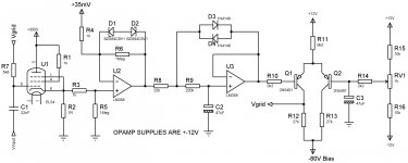
Here is the current setup I'm simulating. I've tried to optimise each stage for symmetry. The first stage only needs to get as symmetrical an output as possible so the second stage has an easier life clamping to a highly symmetrical signal to charge and discharge the integrating cap.
I keep describing that stage as an integrator even though it is not the classic integrator configuration. However its job is effectively to integrate the signal fed into it to produce an error signal so the use of the name seems to fit.
The simple output stage seems unnecessarily fussy in its bias voltage control but it has been optimised to make the second stage work around 0V with the selected bias current control voltage, (35mV at the moment), as much as possible. That way the system is set at start up and takes very little time to stabilise. I would think that will change once the valve warmup has to be taken into account though it shouldn't produce any dramas. Something I am going to try is to set it around the cathode bias voltage level which I think could possibly reduce drift during drive conditions. I'll flesh this stage out a bit more to offer better gain when I can.
Attachments
Yes I did look at that. The programming would be easy but I suspect the practicalities of the method, collecting all of the relevant signal info from the amp circuitry and making decisions based on it, wouldn't be as simple. It could be say Arduino based in the first instance depending on how high speed the working needs to be. My guess is it would benefit from using something a fair bit faster.
You need a way of reading the current through the valve which we have with our existing cathode resistor and an ADC (maybe already in the Arduino). You need circuitry to control the grid bias which is easy and which we already have the basis of. However, you then need a way of identifying when the valve is in its true quiescent state to read the instantaneous bias current which is not so easy if you want adjustment to be more or less continuous. During signal bursts you have the same problems that an analogue system has, if the bias drifts how do you identify that and adjust it while the signal is lashing around without making possibly wrong assumptions about the current bias level?
I would have thought that at its simplest level you would need inputs of the signal voltage and the bias current level and an output to the valve grids for the bias voltage. Buffering and level shifting circuitry would need to be built for that. You would need to spot zero crossing for the signal voltage in software and at that exact moment read the bias current. A system to average a number of rolling readings in both directions may be of benefit there. This would then need to generate an adjusting voltage which would be applied to the valve grid. It may not be necessary to force the system to adjust based on every zero crossing reading, i.e. keep the setup completely continuous. Perhaps just do it at the start of a fixed period window of something like a few tenths of a second. The loop time from reading through adjusting to responding would become a factor and could lead to some awkward effects such as overshoot or ringing or even oscillation. There will no doubt be other effects to be identified and worked around. It's doable but would take careful setup.
I believe Marshall have a system in use in some of their models which they have based around a digital processor. From what little I can glean they seem to read the bias state when definitely no signal is being applied and then simply use the processor to work to that set level to keep the bias constant from then on until you next physically choose to read it again. If that view is accurate then it seems no better than a more convenient version of what we have at the moment, a set level on a pot which is intended to stay constant. The main improvement seems to be that you don't need to go into the amp to read the bias level and adjust a pot as the amp does the reading and setting for you when you tell it to.
I think their system also means keeping the bias voltage set to the quiescent level not reading and altering the bias current and adjusting that directly which is the point of the whole exercise to my mind. They sort of cop out by stating that they want to keep the "feel and dynamics" of the original bias method. I'm not convinced that is the whole truth. Is there genuinely a meaningful feel and dynamic of a bias system that slowly drifts off its set value? I think true instantaneous reading and adjusting of the bias current digitally may be a more involved task than might be first thought.
A system which is simply set to hold a voltage steady to a preset constant level is not the same as a self adjusting setup which reacts to any and all changes within the system in real time. Also it has to be said that the analogue methods we can employ are relatively cheap and easy to implement, (though not necessarily to optimise). They give definite improvements over the existing standard bias methods in terms of stability of bias current over time against all changes in the system, particularly in guitar amps. Also the control theory feedback mechanisms are already well established though in our case they may not be crucial as our responses are slow rather than fast.
I may be completely wrong on some of this as there is not too much info out there either from Marshall or on the digital methods which could be used, if anyone else has any knowledge or thoughts on this I would love to hear it, it may change my mind on the matter. With more understanding it may be something I will look at in the future, all of this stuff grabs me at some time, but for the moment I think a simple analogue method is probably my best bet. (And it's fun to tinker with.)
Hi,
You might want to have a look at this MicroProcessor controlled Bias Kit, from the German supplier Tubeland tubeland
i.e. http://www.tubeland.de/product_info.php?products_id=33&MODsid=56fffd0e2541afdec67e3f40ff13af48
(I guess you have to use Google Translate, if you're not fluent in German") ).
).
It is a complete kit for autobiasing of 4 Tubes (a 2 Tube kit is also available) for a very modest price (€ 50.- for the 4 Tube version (including components, but you can also buy only the PCB an the preprogrammed uProcessor for € 22.- ).
The circuits works as follows;
1) First, it waits 30-45 seconds (to allow the filaments of the tubes to stabilize; same for the AnodeVoltage of the power tubes).
Optionally, you can also hook up a Soft Start circuit, wich gets its command from the Microprocessor.
AND
2) It checks whether there is indeed sufficent (and stabilized) Anode Voltage to the power tubes.
Next, it starts regulating to a preset negative Bias ( i.e.Cathode bias current, (preset by a multipostion switch). It measures the voltage differental across a small (e.g 1 Ohm, cathode resistor for each tube).
3) Finally, it checks whether you have some audio voltage at the secondary of the OPT.
4) If so, it will now go into a Mode "Freeze"(fixed bias per tube, as long as there is a music signal at the OPT. If there's a long period (say 5 minutes) without music, the regulation circuit becomes active again.
It has 4 LEDS for the 4 tubes to indicate whether they are within a preset Bias current window.
If not, a LED (per tube) indicates the faulty Tube and switches off the offending Channel of by going to max negative bias voltage.
There are also LED's to indicate whether the circuit is ready to regulate and whether it is frozen into a predetermined fixed bias.
I would appeciate your views on the above circuit, especially whether it is sufficiently FailSafe.
(My only worry at th moment is whether the Cathode current Sensing circuit (across a ONE Ohm cathode resistor for each output Tube) has a high enough input impedance in order to NOT influence the audio signal of the amplifier).
Also the microprocessor should not induce interference into the Audio circuit (there are2 suppressor coils and RC circuits to cater for this.
I have a PrimaLuna Amplifier (4x KT88) with a very simple servo autobias (which works nicely), but this Servo Autobias is not fully independent of the audio signal, so in theory the above circuit of Tubeland.de would be better. (Just curious how it behaves)!
I would welcome you opinion on this kit (I asked this question on the Dutch forum Circuitsonline as well, but I got only negative remarks from Luddites who feel that semiconductors and Tubes do not go together, at all.
This is clearly not the opinion of renowned makers like AudioResearch who nowadays use their own versions of automatic autobias circuits e.g. in the REF160M main amplifier.
Audio Research Announces It's Most Musical Amplifier Amplier, the REF160M Mono Amplifier | StereoNET Australia
I'm looking forward to hear your opinion!!
You might want to have a look at this MicroProcessor controlled Bias Kit, from the German supplier Tubeland tubeland
i.e. http://www.tubeland.de/product_info.php?products_id=33&MODsid=56fffd0e2541afdec67e3f40ff13af48
(I guess you have to use Google Translate, if you're not fluent in German
).It is a complete kit for autobiasing of 4 Tubes (a 2 Tube kit is also available) for a very modest price (€ 50.- for the 4 Tube version (including components, but you can also buy only the PCB an the preprogrammed uProcessor for € 22.- ).
The circuits works as follows;
1) First, it waits 30-45 seconds (to allow the filaments of the tubes to stabilize; same for the AnodeVoltage of the power tubes).
Optionally, you can also hook up a Soft Start circuit, wich gets its command from the Microprocessor.
AND
2) It checks whether there is indeed sufficent (and stabilized) Anode Voltage to the power tubes.
Next, it starts regulating to a preset negative Bias ( i.e.Cathode bias current, (preset by a multipostion switch). It measures the voltage differental across a small (e.g 1 Ohm, cathode resistor for each tube).
3) Finally, it checks whether you have some audio voltage at the secondary of the OPT.
4) If so, it will now go into a Mode "Freeze"(fixed bias per tube, as long as there is a music signal at the OPT. If there's a long period (say 5 minutes) without music, the regulation circuit becomes active again.
It has 4 LEDS for the 4 tubes to indicate whether they are within a preset Bias current window.
If not, a LED (per tube) indicates the faulty Tube and switches off the offending Channel of by going to max negative bias voltage.
There are also LED's to indicate whether the circuit is ready to regulate and whether it is frozen into a predetermined fixed bias.
I would appeciate your views on the above circuit, especially whether it is sufficiently FailSafe.
(My only worry at th moment is whether the Cathode current Sensing circuit (across a ONE Ohm cathode resistor for each output Tube) has a high enough input impedance in order to NOT influence the audio signal of the amplifier).
Also the microprocessor should not induce interference into the Audio circuit (there are2 suppressor coils and RC circuits to cater for this.
I have a PrimaLuna Amplifier (4x KT88) with a very simple servo autobias (which works nicely), but this Servo Autobias is not fully independent of the audio signal, so in theory the above circuit of Tubeland.de would be better. (Just curious how it behaves)!
I would welcome you opinion on this kit (I asked this question on the Dutch forum Circuitsonline as well, but I got only negative remarks from Luddites who feel that semiconductors and Tubes do not go together, at all.
This is clearly not the opinion of renowned makers like AudioResearch who nowadays use their own versions of automatic autobias circuits e.g. in the REF160M main amplifier.
Audio Research Announces It's Most Musical Amplifier Amplier, the REF160M Mono Amplifier | StereoNET Australia
I'm looking forward to hear your opinion!!
- Status
- This old topic is closed. If you want to reopen this topic, contact a moderator using the "Report Post" button.
- Home
- Amplifiers
- Tubes / Valves
- Broskie auto bias