As an engineer, it is important to evaluate the cost to benefit ratio, no? At what cost to complexity and reliability comes a benefit that may (or may not) be significant. It is that aspect I was questioning.
Sure, but one has to look at the requirements to determine what a benefit is. In this case it is a requirement that I learn. It is not a requirement that every component make a major improvement in the amp's performance. I don't get to do much analog design at work, so this is fun and informative for me.
Also, I spent nearly a grand on these output transformers. I am committed to taking no shortcuts on this one. Having bias voltage automatically set itself and stay constant regardless with signal seems like a worthy goal if I get to learn in the process of making it.
Just a side observation.
Gary Pimm has some interesting observations about the benefits of screen regulation as opposed to simply tying the screens to B+, he measured better results with the screen tied straight to B+.
Shoog
Was this directed at the amp I am building?
Sure, but one has to look at the requirements to determine what a benefit is. In this case it is a requirement that I learn. It is not a requirement that every component make a major improvement in the amp's performance. I don't get to do much analog design at work, so this is fun and informative for me.
Also, I spent nearly a grand on these output transformers. I am committed to taking no shortcuts on this one. Having bias voltage automatically set itself and stay constant regardless with signal seems like a worthy goal if I get to learn in the process of making it.
Yes, and that is the beauty of a hobby. I made my comments in reaction to Broskie's writing in general, and not your application in particular. In fact the followup article won me over to his concept.
That followup circuit is the one I most prefer, BTW. I have a PP EL84 amp chassis that I've been pondering together with a big cigar box full of OS EL84s. I'm interested enough in this concept to try the original garter on one channel and the "revisited" circuit on the other. The cool thing about the EL84 is that one only gives up about 11 volts of plate voltage with the original garter circuit.
Last edited:
I had noticed in your other thread that you were discussing different approaches to screen supplies - thought you might be interested in another engineers experience about what he found worked best.
Shoog
Thanks, the only problem with connecting screen to B+ in that amp is that it would effectively create ultralinear-type feedback at the screen because of the cathode feedback. It would linearize things but would reduce gain and it already takes ~200Vrms to drive the output tubes to clipping. I don't know if I want the driver clipping first. It's definitely worth considering in other amps, though.
I wanted to drop the screen voltage to keep the load line above the knee of the curves and be easy on the screen.
Yes, and that is the beauty of a hobby. I made my comments in reaction to Broskie's writing in general, and not your application in particular. In fact the followup article won me over to his concept.
That followup circuit is the one I most prefer, BTW. I have a PP EL84 amp chassis that I've been pondering together with a big cigar box full of OS EL84s. I'm interested enough in this concept to try the original garter on one channel and the "revisited" circuit on the other. The cool thing about the EL84 is that one only gives up about 11 volts of plate voltage with the original garter circuit.
I would definitely consider cathode bias in an EL84 amp.
I would definitely consider cathode bias in an EL84 amp.
Why? What's wrong with fixed bias and EL84 s?
<snip> Having bias voltage automatically set itself and stay constant regardless with signal seems like a worthy goal if I get to learn in the process of making it.
I'm wondering if microprocessor controlled biasing might be of interest here using something like the Arduino or a Basic Stamp? Obviously you'd need and ADC, DAC (I2C) and some good analog circuit design to tie it all together. You could take it a bit further and indicate when a tube was approaching the limit of bias circuitry or was failing for a variety of reasons observable by twiddling the bias voltage and measuring cathode current.
Take a look at the schematic for the old Berning/Audionics BA-150. Since this was 1977, he used a pile of logic chips rather than a uC. It was a clever approach- the circuit acted much like a sample and hold. When the input dropped below a certain level, the circuit would check the idle current and adjust the bias. When the music started, the circuit was inhibited and kept the bias constant at the last value.
Other good analog op-amp based approaches can be found in Morgan Jones's "Valve Amplifiers" and Menno Vanderveen's "High End Valve Amplifiers 2." If each tube is controlled well, you don't need a differential circuit.
Other good analog op-amp based approaches can be found in Morgan Jones's "Valve Amplifiers" and Menno Vanderveen's "High End Valve Amplifiers 2." If each tube is controlled well, you don't need a differential circuit.
Many of these schemes for bias servos for Class AB amps depend upon clipping the cathode signal at 2 x the idle bias level to match the natural clipping which occurs at tube cut off, that is, the monitored cathode signal is clipped such that is swings symmetrically either side of the idle point.
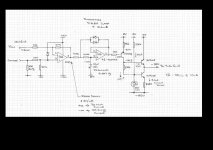
For simplicity I like the Menno/Guido scheme where signal is clipped in a very narrow window around the idle voltage. They do this with a diode clamped integrator which means that you need a enough gain after the integrator for a 0.6V max signal to achieve the full bias voltage output. I also like their bias output amp, why? because it is current source loaded which isolates the bias voltage output from any residual noise on the -ve rail.
Here is a part schemo - Mods Alert, please remove post if deemed inappropriate.
Cheers,
Ian
Attachments
I realized I forgot to post a link to the TubeCad blog article that explains the design of the master bias control. That is here in case anyone missed it.
Microprocessors would be a more technically perfect solution but I try to stay with simple analog circuits if they do as good a job. The problem with microprocessors is the development tools become obsolete. I have a chip programmer I built in college 8 years ago and I can't run the software anymore because the executable only runs with XP and earlier. I'll have to give it some thought.
A clipping autobias circuit that clips within a more linear portion of the tube's operation may be a really good approach if there is little assymetry around the operating point in the autobias circuit's 'window'. Might get less error all around.
I expect all of these autobias circuits, clipping circuits or the non-clipping Broskie circuit, to function well in this amp since the local feedback in the output stage makes the KT88s have very linear triode-looking characteristics with mu=2. Most of the errors in these bias circuits under dynamic conditions come from even order distortion produced by the tube when it is operating in the circuit's 'window'.
Hey, let's not drag poor Blumlein's name through it. I don't know how Broskie accidentally attached Blumlein's name to the circuit, but the garter circuit was created by Jean-Victor Martens in patent FR64203E, not by Blumlein!Blumlein's circuit is very elegant in its simplicity and offers pretty good performance, but not as good as the circuits Broskie fleshes out.
Martens or Blumlein, I don't know
regarding paralel pushpull
maybe I'm completely wrong, but I suppose with the Blumlein you could use non matched tubes in paralel
wouldn't both of the two tubes in paralel try to 'allign' with the other two tubes .....not perfectly, but in a sense be 'auto-matched'
regarding paralel pushpull
maybe I'm completely wrong, but I suppose with the Blumlein you could use non matched tubes in paralel
wouldn't both of the two tubes in paralel try to 'allign' with the other two tubes .....not perfectly, but in a sense be 'auto-matched'


Hi Folks:
I know it's an old thread, but I just found it. Here’s my board layout based on a variation of the Vanderveen circuit found at the RMS Acoustics & Mechatronics website Motional feedback intro. According to the site, RMS is the brainchild of Rob Munnig Schmidt, professor in Mechatronic System Design at Delft University of Technology. I have no affiliation but liked the explanation and simplicity of his version so I decided to start with it rather than one of the other versions. Thanks to Mr. Schmidt for making it available on-line.
A couple things to note:
1. The board includes a regulated power supply for the +- 15v OpAmp supply and a separate adjustable regulated supply for the negative reference voltage. Both start with AC taken from the 6.3Vac filament supply and go through a quadrupler to get raw ~+-17.6Vdc.
2. The board includes a simple unregulated power supply for the negative grid bias voltage. A regulator could be squeezed in, but since I’ve seen countless schematics with just plain CRC filtering for the bias supply I decided not to sweat it for this round. Plus, I wanted to be able to run a variety of tubes, some with high bias requirements (6AS7 for example), and a discrete transistor/MOSFET HV regulator would take more fiddling to fit.
3. The board is 2”x4”, manages two tubes and is laid out one-sided so I can make it with the laser printer + photo paper + iron method. (After much trial and error I’ve worked out the bugs and get reliable good looking results with this method. The trick is to NOT overheat the toner and NOT over compress it.)
Any comments on improvements or flaws?
Attachments
Last edited:
- Status
- This old topic is closed. If you want to reopen this topic, contact a moderator using the "Report Post" button.
- Home
- Amplifiers
- Tubes / Valves
- Broskie auto bias