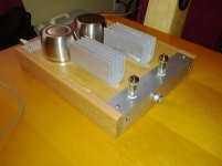
The design for this amp started as a scrapbox amp. A lot of ideas and sources came together in its design. The primary factor was actually two torroid transformers that didn't have a use. They were 120:14v with single primaries and dual secondaries, which are for the most part useless for tubes. I used RightMark audio analyzer to do a frequency response and they were totally linear through the audio band, at least at the low power my soundcard put out. As a comparison, Hammond 125 transformers showed noticeable roll-off at high and low frequencies, so I'm reasonably confident that theoretically these are OK.
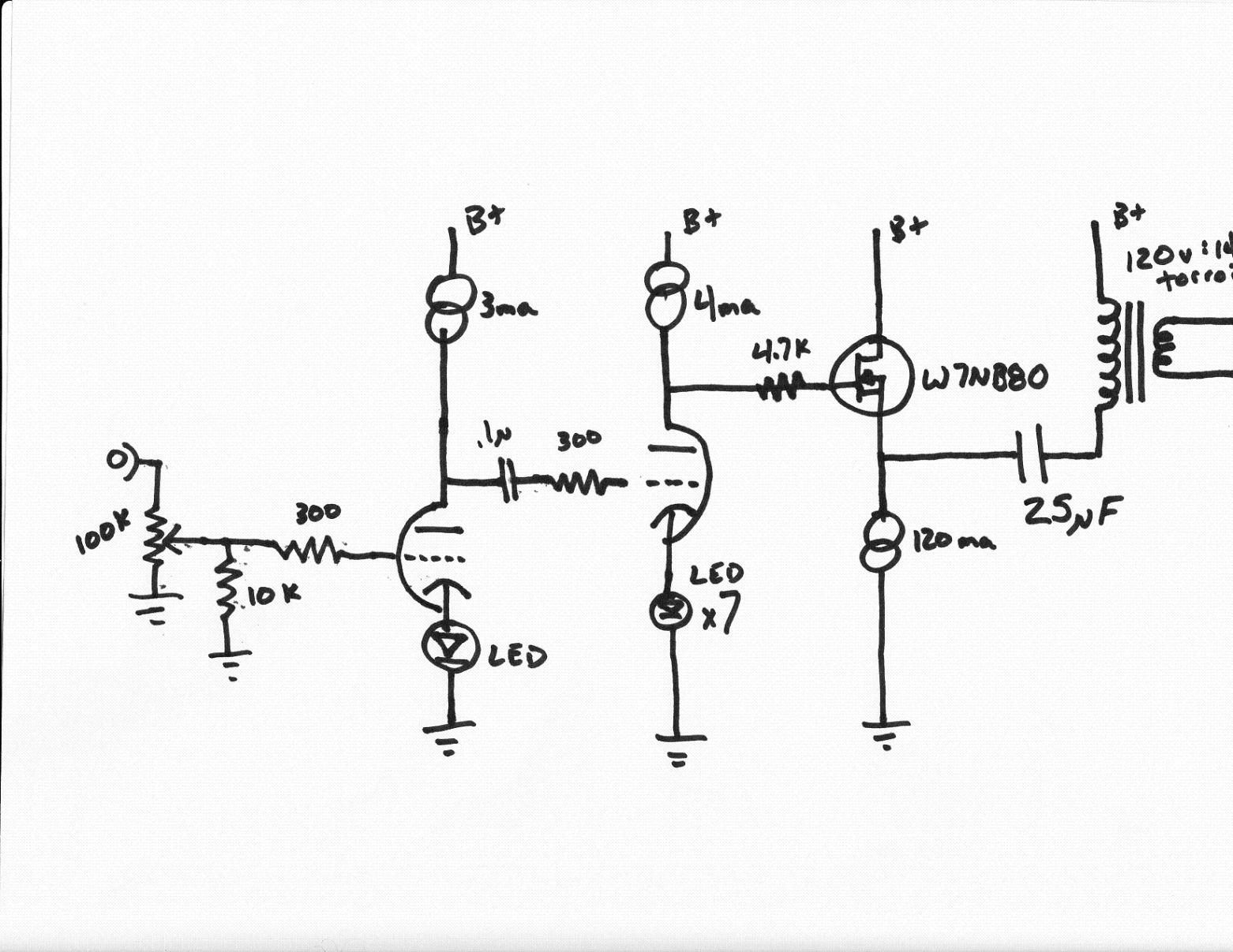
Next up, how to design the output stage. The reflected impedance with an 8 ohm load would be about 480 ohms, too low for most any tube, at least the ones I could afford. So I decided a MOSFET would be put into service as a follower with a decoupling capacitor to keep DC out of the transformer. The follower topology keeps Miller capacitance low. I found cheap W7NB80 high voltage MOSFETS I found for $1 each with heatsink and thermal pad at Goldmine Electronics. I also found 100 1.8uF 400v capacitors for $10 as well. I decided on a B+ of about 200v to stay within the transformer's spec. Honestly, I could have gone with twice the B+ but I didn't want to have to use more expensive higher voltage parts. I used a CCS on the source set to 120ma. The blocking cap is made up of 14 1.8uF caps to give me about 25uF for a cutoff frequency of about 10hz.
For the gain stage(s) I needed a gain of about 100 to get full swing (realistically there's about 10 volts at each end that are lost due to the MOSFET and CCS). I found the neat little 13DE7 (a 6DE7 or 10DE7 could be used with different heater voltages) that has two dissimilar triodes in it. The first is lower power triode with a gain of about 17 and the second is a higher power triode with gain of 6. I used a CCS on both with LED bias, one cheap red LED on the first gain stage and seven in series on the second. This gives about 1.9v and 13v on the biases. The two stages are capacitor coupled, with the MOSFET directly coupled with the anode of the second stage. A linear 100K pot with a 10K bypass gives a pseudo-log volume control. All together, very simple and straight-forward single ended design.
The PSU is my old standby. I had a dozen PCBs made up and use them with all my amps. It's a simple MOSFET follower with a zener string used as a voltage reference. I used cheap photoflash capacitors and the same W7NB80 MOSFET. The PSU also gives me a 50v tap for heater lift.
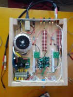
The whole thing was done point to point with co-ax for the input signal wiring and a tight twist on the heater AC wires. It fired up first try with no problems. It puts out probably about 5-8 watts, about the same as the T-amp it will replace.
Next up, how to design the output stage. The reflected impedance with an 8 ohm load would be about 480 ohms, too low for most any tube, at least the ones I could afford. So I decided a MOSFET would be put into service as a follower with a decoupling capacitor to keep DC out of the transformer. The follower topology keeps Miller capacitance low. I found cheap W7NB80 high voltage MOSFETS I found for $1 each with heatsink and thermal pad at Goldmine Electronics. I also found 100 1.8uF 400v capacitors for $10 as well. I decided on a B+ of about 200v to stay within the transformer's spec. Honestly, I could have gone with twice the B+ but I didn't want to have to use more expensive higher voltage parts. I used a CCS on the source set to 120ma. The blocking cap is made up of 14 1.8uF caps to give me about 25uF for a cutoff frequency of about 10hz.
For the gain stage(s) I needed a gain of about 100 to get full swing (realistically there's about 10 volts at each end that are lost due to the MOSFET and CCS). I found the neat little 13DE7 (a 6DE7 or 10DE7 could be used with different heater voltages) that has two dissimilar triodes in it. The first is lower power triode with a gain of about 17 and the second is a higher power triode with gain of 6. I used a CCS on both with LED bias, one cheap red LED on the first gain stage and seven in series on the second. This gives about 1.9v and 13v on the biases. The two stages are capacitor coupled, with the MOSFET directly coupled with the anode of the second stage. A linear 100K pot with a 10K bypass gives a pseudo-log volume control. All together, very simple and straight-forward single ended design.
The PSU is my old standby. I had a dozen PCBs made up and use them with all my amps. It's a simple MOSFET follower with a zener string used as a voltage reference. I used cheap photoflash capacitors and the same W7NB80 MOSFET. The PSU also gives me a 50v tap for heater lift.
The whole thing was done point to point with co-ax for the input signal wiring and a tight twist on the heater AC wires. It fired up first try with no problems. It puts out probably about 5-8 watts, about the same as the T-amp it will replace.
Attachments
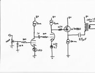
The 120ma CCS is the standard LM317 and 10M45s cascode (Fig. 13C) used by Walt Jung in his two part articles:
http://waltjung.org/PDFs/Sources_101_P1.pdf
http://waltjung.org/PDFs/Sources_101_P2.pdf
The 3ma and 4ma are the same thing except with a LM334 in place of the LM317, except with an appropriately changed set resistor and the pins swapped (since the pinout is 180 degrees from the 317). You could use any high voltage CCS, even a simple 10M45s with two resistors. I just had three dozen CCS PCBs made up along with a dozen power supply PCBs, so it's very easy for me to build one up quickly.
The power supply toroid is an Antek 100VA 175v model. Inexpensive and high quality.
Also, I left out a resistor in the schematic. An additional 300K resistor needs to be tied from the junction of the 0.1uF cap and the 300 ohm resistor to ground in order to reference the grid of the second stage to ground.
The pentode would need to be triode strapped or else you would need some global feedback to linearize the pentode. The reason I chose the tube I did was because the first stage with a gain of 17 would take the approximately .7v input signal and amplify it to about 12 volts. The second stage has a bias of 13 volts from the LED string, so it can handle up to 13 volts of input and the gain of 6 will drive it to +/- 78v maximum. I also chose the tube because the tube would bias easily at 2v with a LED.
I'm not sure what the characteristics of the pentode stage will be if they are strapped into triode operation. The first stage mu of those tubes is pretty high, about 70. You might need to drop some amplification with voltage divider, or use global feedback.
The MOSFET can easily be driven by a tube at audio frequencies. If you're worried about gate capacitance, use a MOSFET like the IRF820 that has lower capacitance and use a lower value of gate stopper resistor, say 1K instead of 4.7K (I used 4.7K because I have a large collection of old-school carbon resistors from 40 years ago, quite useful as grid stoppers).
Nope, divider resistors are not mislabled. They are not used for the CCS, they are used as a voltage lift for the heaters, about 50v above ground. The CCS doesn't have a voltage reference - it doesn't need one since it only cares about current. The MOSFET gets its DC voltage from the anode of the second tube stage, which based on the datasheet should be about half B+ with 4ma and -14v on the grid (it's about 90 volts in real life).
what i mean is that the 100k and the 300k should be interchanged, the 50volts taken from the junction of 300k and 100k....
any reason why the isolation output traffo is returned to B+ instead of ground?
lastly, i see in you drawing that there is no grid leak resistor to ground for the second triode, did you build your amp like that? just curious.....
any reason why the isolation output traffo is returned to B+ instead of ground?
lastly, i see in you drawing that there is no grid leak resistor to ground for the second triode, did you build your amp like that? just curious.....
Yeah, the 100K and 300K got transposed on the schematic, they're correct in real life. Also, in post 4 I noted that I accidentally left the grid leak resistor out of the schematic. If you look at the picture of the underside of the actual amp, there's a small resistor on the right side of the tube sockets that runs to the ground bus bar - that's the grid leak resistor, it's a 300K IIRC.
I connected the parafeed to the B+ because that way the amp is a constant current draw amp. It makes life easier for the power supply, and should reduce noise. It will work hooked up either way, but I think that it's a bit more efficient since there is no current in addition to the CCS.
I connected the parafeed to the B+ because that way the amp is a constant current draw amp. It makes life easier for the power supply, and should reduce noise. It will work hooked up either way, but I think that it's a bit more efficient since there is no current in addition to the CCS.
Yeah, the 100K and 300K got transposed on the schematic, they're correct in real life. Also, in post 4 I noted that I accidentally left the grid leak resistor out of the schematic. If you look at the picture of the underside of the actual amp, there's a small resistor on the right side of the tube sockets that runs to the ground bus bar - that's the grid leak resistor, it's a 300K IIRC.
I connected the parafeed to the B+ because that way the amp is a constant current draw amp. It makes life easier for the power supply, and should reduce noise. It will work hooked up either way, but I think that it's a bit more efficient since there is no current in addition to the CCS.
thank you for your response, now i understand your design better.....
")
Shoog - I did a little critical listening tonight. Speakers were bookshelves with Peerless woofers, Usher tweets as designed by Wayne J. at the former speakerbuilder.net:
The PeeCreek
Source was mp3s from a Galaxy Nexus. I listened to a variety of material and the one thing that stood out was the mediocre quality of the cell phone. The amp is good enough that it isn't the weak point in the chain right now.
I tried with my computer speakers as well, Tang Band 3" Bamboo drivers in a tapered quarter wave pipe. They're very lively, with a definite tone to them (probably due to their solid wood construction and limited frequency range. That tone came right through, telling me that the amp is fairly neutral and not a weak point. Eventually, this amp will be used with the larger bookshelves as an amp for my computer.
Next up, how to design the output stage. The reflected impedance with an 8 ohm load would be about 480 ohms, too low for most any tube, at least the ones I could afford.
Just an afterthought:
Wouldn't a tube cathode follower be feasable instead of the MosFet ?
Assuming gm of - say -15 mA/V should give Z=1/gm=66 ohms for the CF.
120mA is also well w/in the range of many sweep tubes.
I've done just that recently, albeit with a 240V/24V Xfmr.
A tube cathode follower would work just as well, but because there is no voltage amplification, I doubt there would be a sonic difference. I think Tubelab would agree that a mosfet follower doesnt color the sound. I just scaled up his Powerdrive to the next level. There would be several diadvantages however. First, tubes cant swing as far to the rails, so that may limit power. Second, a big tube requires a big heater, which is just wasted power if not needed. Third, the Mosfets were a buck each, less than the cost of a good socket. This amp was inexpensive and I didnt want to spend alot on parts I didnt have on hand.
6N1P_6N6P version
Hi, i've tried your design concept, i dont have dissimilar triode at hand so i tried with my available resources too....see schematics...but i have some problems....at low volume...it's sound okay but when i go higher there's some annoying sound just like pops,scratches etc.but no hum....and one thing i've noticed is the 3 green bias LEDs on 6N6p are blinking/dimming but the 5.8v read out stays...what might have cause this thing...I've increased the current for about 7ma but no effect on the sound and the dimming.
The led on 6n1p is stable...at low volume LEDS has stable light. would it be clipping or whatever..please help me out...what wrong on the schematics
Attachments
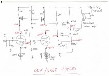
you can try increasing the current on the 3 seriesed green leds...a resistor from the B+ of say 47k 2 watts ought to increase the led current to about 10mA...
maximum voltage swing happens at 1/2 Vcc of B+ to the blocking cap, 20ufd..
Hi sir tony thanks for dropping by...i've tried increasing the bias current to 7ma by adjusting the source resistance of the CCS...still no effect but increased the plate voltage of 6n6p at point B to 167v...by lowering the ccs current i can achieved 1/2 B+ at point B...and also to point C (output)
I will try the feed resistor you propose and see what the effect...
One thing with 6n6p at 5.8 v input and gain of around 20 or 22 (=116v) will it be enough for a full swing on the trafo?
the load seen by your output stage is about 1400k, how low does your B+ drop when you increase the volume?
assuming that your B+ stays 255volts, the ac out is about 85 volts so that output power is about 5 watts.....less if your B+ sag.....lesser still as you deviate from 1/2 B+.....
having 2 stages of tubes, gain is plenty.....
gain of the 6N6 is limited by the mu of the tube...the 5.8v is the bias needed to get the target plate current....it is not an input voltage...
6n1p has a mu of 33 and the 6H6/6N6 has a mu of 22, so theoretically you have a voltage gain of 726....actual voltage gain is much lower....
Last edited:
- Status
- This old topic is closed. If you want to reopen this topic, contact a moderator using the "Report Post" button.
- Home
- Amplifiers
- Tubes / Valves
- New amp: 13DE7 SE hybrid