Another tube that seems useless at first glance is the 6LE8 color matrix demodulator tube.
The 6LE8 is a typical "dual control pentode" except that G3 and the plate has been split in two.
The dual control pentodes go back to the WWII vintage 6AS6. These usually have a robust screen grid which can (and does) eat all the tube's cathode current when G3 is used to cut of the tube. They can be used for Variable Gain Amplifiers, so I experimented with them while researching circuits for a vacuum tube based music synthesizer.
The 6LE8 and a few others have the G3 and plate divided so that there is a common control grid (G1), and two separate G3's, one for each plate. These can steer the beam toward each plate, or cut it off completely forcing all cathode current to G2. This makes for some useful music synthesizer circuits.
In the pre-decimal days, I’d spend my 2 shilling pocket money on a bag of pulled valves from a local TV repair shop, unfortunately not knowing how to use them, but just enamored by them through looking in the backs of old radios and TVs. I still have those tubes, and there are a lot more potentially useful tubes there, than I thought before discovering this site. There are a fair few PCF80 (8A8/9A8) and ECF80 (6BL8), with nary a mention after looking through the thread. But they have a following for being a 7199 replacement, and had some commercial audio uses.
In fact, it sometimes seems like hardly any tubes are worthless!
In fact, it sometimes seems like hardly any tubes are worthless!
Last edited:
In fact, it sometimes seems like hardly any tubes are worthless!
Can't find too many uses for the HV rectifier tubes from TV sets. The 1B3, 1G3 tubes from B&W TV's are good for about 15KV at a few hundred microamps.
The 3A3 and all of it's low X-ray emission offspring found in color TV's are good for 25 to 27 KV at 1 to 2 mA.
The 6BK4 high voltage regulator has found use in DIY X-ray machines, but I don't think too many people are building them. Mu of 2000, plate voltage 30 KV. They won't even draw plate current on less than 2 KV.
6BN6 gated beam discriminator
Now if we could just convince the C______ that it was a cure for Covid. Would be such a pleasure to see the world supply bought up overnight.
6BK4 may have some interest develop soon. Some researchers found that a HV field combined with a magnetic field can cure diabetes in a few days. Just sleeping in the field works apparently (link below).
In any case I think it would be interesting to make a HV LF amplifier with them for immersive electrostatic use (alpha waves).
Remote control of blood sugar: Electromagnetic fields treat diabetes in animal models: Study suggests EMFs alter redox signaling to improve insulin sensitivity -- ScienceDaily
Last edited:
6BN6 gated beam discriminator
Somewhat useful for making square waves from semi sinusoidal waves. Unfortunately not quite good enough to handle my lousy guitar playing. The idea was to feed the resulting square waves into a flip flop for dividing the frequency by two.
Were you trying to make a primitive tube version of a dBx 120A?
Nothing quite that complicated.
I have been building a modular music synthesizer slowly over the past few years. Many of todays "oscillators" have a secondary "sub" output that's one or two octaves below the main output. Since the main oscillator has a square wave output, it's pretty easy to make the sub output with a dual flip flop chip.
Somewhere in a dark corner of my brain resides this idea of making a vacuum tube music synthesizer, along the lines of a MiniMoog, but using vacuum tubes for the signal path, and more modern electronics for the control and supporting roles......kinda hard to do a MIDI interface in tubes. I have most of the major building blocks working individually on breadboards, including a "digitally assisted" vacuum tube VCO, with a sub-output.
I got the dumm blonde idea of running my guitar signal through its frequency divider, hence the squarer circuit with a 6BN6, which performs the limiting (squaring) and discriminating function (ditch the quad coil and integrating cap to kill it) in an FM radio or NTSC TV (FM sound). The circuit requires a clean SINGLE FREQUENCY signal to work correctly. Feed it two guitar notes at once, or even some string noise and all sorts of ugly comes out.
Sin Q/2 = +/- 0.707 x SQRT(1+SIN Q )
However there are some issues with this formula. The "1" is the max amplitude of the signal coming in. The SQRT needs to change sign to keep continuity around zero output. It only works for one frequency at a time.
A 6JH8 beam deflection tube set, with a N FDBK circuit, can do the SQRT function. But some kind of derivative detector would be required to flip signs appropriately. There could be a more complex math function that would eliminate the sign flips, I just can't find it yet.
------------------------------------------------
There is a more sophisticated approach that will work for combinations of frequencies simultaneously to halve the freq. The most obvious is the FFT, then shift the coefficients down to half freq., then do the inverse transform. This would only be practical with a digital signal processor with A/D and D/A functions.
-----------------------------------------------------------------------
However, there is a clever version called the FIFO Fourier Transform. It works by just computing the difference in the FFT after each new sample comes in. This will work for either digital or analog implementation. It just requires an analog FIFO memory (minimum N samples for N/2 bandwidth) and it updates the FIFO data with each signal sample time slot, using a multiply and two additions for each memory location. The 6JH8 BDT and a summer can do this readily.
Analog memory would be provided by N sample and hold functions. An analog FET gate multiplexer would cycle around the N locations to update them for each clock cycle. An inverse FIFO transform then translates the stored data back to a signal using the analog multixer to select data to average FIFO locations to halve the frequency. Still complicated, but this appears to be as simple as it gets for a complex signal, and is within the realm of a serious effort.
Last edited:
Sin Q/2 = +/- 0.707 x SQRT(1+SIN Q )
These things are possible, and as stated are easiest done in a DSP using complex math and algorithms far above my current mental processing power.
I just tried the guitar into a 6BN6 tube idea for two reasons, both of which I do a lot......I have a bunch of them, and to see what would happen.
This road has been traveled a lot by the major musical instrument corporations over the past 25 years. The "ideal" product would be a device that you plug a guitar into that outputs MIDI data with zero latency so that a guitar player could play a synthesizer.
MIDI (Musical Instrument Digital Interface) has been around, pretty much unchanged since the mid 80's. The MIDI 2.0 spec just appeared late last year, and much has changed. It will be a while before we see what and how much of it gets adopted by the major manufacturers of music gear.
These devices have existed for 25+ years, but they have been far from ideal, and are constantly improving. Until very recently they all used a special guitar pickup with a separate output for each string. This limits the processing to six circuits that each only see one note at a time. The harmonic content of this signal can be high, and does vary over time, but simple opamp circuitry can be used.
I have two such devices, both quite old and obtained cheap on Ebay. The 15 year old state of the art used 6 identical (except for cap values) circuits that squared up the signal, then attempted to count edges, or measure time between zero crossings. Since the lowest note on a guitar is about 82 Hz this leads to a minimum latency of 12 or so mS which is too much, considering all the other delays in the system. MIDI itself is 31K baud co complex note and control data can bring a 2 to 3 mS delay.
Today there are a few pieces of software that harness the power of a PC with some fancy algorithms that can do a fair job of turning guitar signals into MIDI data from a single sound card input. I tried one of the free trial versions several years ago and it worked Ok, but still had issues and ran the CPU meter up to over 50% on a 4th Gen Core i7 machine.
Several years ago I build a custom guitar with a wired fretboard and some PLL chips. I think that would be the direction I would take if I ever go back to this project. It's still in a box somewhere since I retired and moved 1200 miles nearly 6 years ago.
Doing any of this in tubes isn't going to happen....but vacuum tube music synthesizers have existed since Hammond made one in 1937:
Novachord - Wikipedia
You can buy one today for about $20K and the waiting list is nearly a year long, it seems to use a lot of hard to get tubes, and some must be selected (must be built by a tube rolling audiophile):
Knifaudio
I have been slowly working on one, and so far most of it's tubes come from the $1 list, but one of those lists no longer exists.
Ah-ha! If the sine wave notes are separate, then the 1st equation will work well.
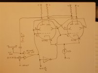
And after thinking about the circuit operation, I don't think any sign flipper is needed, just a tiny bit of overshoot in the Op Amp gets the correct path started on zero crossings. A circuit using 6JH8 beam deflection tubes is attached below. Some DC bias adjusts are likely needed, but grid 1 and deflectors nominally operate around 0 V. An AC only passing cap needed for the - input of the Op Amp along with a 0V bias adjust there. Also a gain adjust for the Op Amp (not shown). 0 V adjusts on the grids and deflectors. { Woops, minor error in the schematic, the dual plate connections need to be dropped I think. Supposed to get X*X + (-X)*(-X ) but that only works with neg. numbers. For this circuit, just use the leftmost X*X plate alone for Fdbk }
If I were going to experiment with analog computing circuits, I would also suggest getting some 6197 tubes (GE ones available cheap in bulk) besides some 6JH8 BDT tubes. The JAN GE 6197 tubes I got a couple of years ago are remarkably consistent and have nice curves. I got them for less than $0.50 each then, when they were on sale. I notice the Ebay ads for qty 50 or 200 of them still have the "make an offer" option.
Attachments
Last edited:
Oh,
I guess if all the plate outputs are individually AC coupled, then X*X + (-X)*(-X) cross coupling will work. But just using the X*X output alone should be fine here.
(the two BDT tubes over the CCS are used to get the grid 1 functions linearized, otherwise one would get X*(X^3/2) due to non-linearity of grid 1. Some cathode degeneration resistors could also be included for even better linearization here. Or, for extreme linearity, a third BDT could be used in place of the CCS in a split cascode like arrangement, so not using grid 1 control at all then. )
Last edited:
I would also suggest getting some 6197 tubes...
The 6197 is a 6CL6 with a cathode coating formulated for "computer use" where long periods of operation (days) with zero cathode current are possible. I have several hundred of each tube, over a thousand 5686 tubes, and several boxes full of other military surplus and computer tubes from the 50's and early 60's. All are well used and have not seen power since the 1960's.
I did experiment with all of these during the development of my vacuum tube VCA (voltage controlled amplifier). The VCA started with a clone of the famous Fairchild 670 compressor circuit, build with genuine 6386 tubes (real expensive now) from the 1960's as my benchmark. I used the same Edcor transformers in each build to remove that variable from the testing. My vacuum tube VCA works as good as the 670 design, but uses a pair of $1 tubes and a pair of mosfet followers for buffers. The vacuum tube Moog ladder VCF (LPF) is not quite up to Moog specs yet though.
If I were to revisit the squarer circuit with opamps, it would be trivial. We (Motorola) developed a circuit in the early 80's to recover a data stream from the discriminator of an FM radio. We called it a "center slicer" and it used a single stage of an opamp or comparator chip. The raw DC coupled discriminator output fed one input, while the LPF (a few Hz corner) filtered signal fed the other input. The output of the chip is the data stream. The corner frequency of the LPF has to be high enough to track frequency drift between the receiver and the transmitter, but low enough not to follow some pretty slow data (around 100 baud). Max data rate was 2400 to 4800 baud.....it was the 80's and we were using 25 KHz RF channels.
The variable mu remote cutoff characteristics of the EF183 (6EH7) tend to generate considerable second harmonic distortion. The level of 2H goes up as the signal level increases. Many listeners find this effect pleasing.
I use similar tubes in my variable gain amp. The 6EH7 is one of the possible choices and it is quite cheap. Like the old Fairchild 670, the even order harmonics are reduced by using balanced push pull operation.
I use similar tubes in my variable gain amp. The 6EH7 is one of the possible choices and it is quite cheap. Like the old Fairchild 670, the even order harmonics are reduced by using balanced push pull operation.
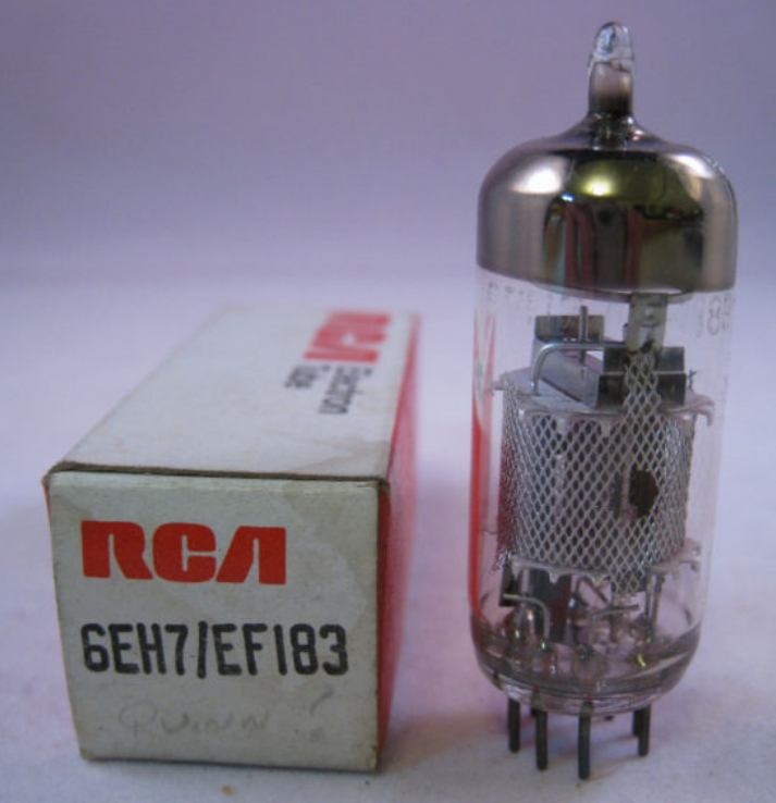
As balanced operation from XLR outputs of many sources (eg.CD players, etc) are already built in, there is no need for additional phase splitters from unbalanced RCA sources-it's already done for you. So I use two EF183's each driven from their two XLR outputs in a fully balanced p/p arrangement driving a p/p output pair of EL34's - thus completely minimising even harmonic distortion.
21LG6A - Have a collection of them. A few posts in this thread mention them so I assume they would be a decent tube to build an amp around.
For playing around I have a bunch of 19.5vdc/6.7A power bricks around (Dell computer bricks). Are those suitable for driving the heaters?
For playing around I have a bunch of 19.5vdc/6.7A power bricks around (Dell computer bricks). Are those suitable for driving the heaters?
Good tubes!6EH7 is equivalent to EF183, see:
EF183 and 184 are quite cheap tubes here also, as are their Russian equivalents, 6SH51P and 6SH15P.
Best regards!
In my experience, these EF184 family have less thermal noise (hiss) than most "normal" non-frame grid tubes***, perhaps due to relatively high gm, but have more microphonics, higher in frequency
Absolutely no trouble with Hi-Fi separated cabinet, but perhaps this will be a issue in a guitar amp or maybe phono preamp
***in some amp using it, I put a headphone directly to the output, and perceived clearly the volume potentiometer increase of noise, even far from 50% "output" (50% resistance) in a 50k log potentiometer, so the self noise from tube is significant less than 12k5 resulting R (input of potentiometer shorted)
Like some quiet semiconductor preamp (not the quietest, but a good one)
operated near 7mA -2Vg 150Va/Vg2 (triode mode)
21LG6A - Have a collection of them. A few posts in this thread mention them so I assume they would be a decent tube to build an amp around.
For playing around I have a bunch of 19.5vdc/6.7A power bricks around (Dell computer bricks). Are those suitable for driving the heaters?
Looking at it, it has similar specs to the 6KD6 so a pair can make a good 80W as triodes into a 1k plate to plate load with 320V ot so on the plate. Twice that as pentodes with more voltage and a different load.
19.5V is a little low for the heater which wants 21V, but it should be close enough.
My21LG6A - Have a collection of them. A few posts in this thread mention them so I assume they would be a decent tube to build an amp around.
For playing around I have a bunch of 19.5vdc/6.7A power bricks around (Dell computer bricks). Are those suitable for driving the heaters?
 about heater:
Since you don't will use this tube in a TV with high horizontal deflection current pulses (and voltages), basically will be very fine.
I use the 40V PL509 with 35V for years and seems to last forever
- Home
- Amplifiers
- Tubes / Valves
- Those Magnificent Television Tubes