Yes, certainly a lower Zpri OT will allow one to make more power out for a given B+ range.
If one has a KV power supply however, then going to a higher Zpri WILL allow more efficiency and power output, providing the tube and OT can take it. HV snubbers becoming a very good idea.
The optimum Zpri OT for power out will usually be lower than the Zpri for minimum distortion.
If one has a 100W 5K OT to start with, then one can still optimize for whatever by choice of tube. With wired output tube sockets, one can try out a range of Sweep tubes, since most have somewhat similar pinouts. Adjustable biasing of course.
Listening to the result of course finally taking precedence.
--------------------------------
He also wanted the output stage distortion to be so low that it could cancel (2nd H) against the driver stage dist.
--------------------------------
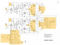
I'd like to see a PC mono-block board offered along the lines of the Lafayette KT-550, but for Sweep tubes. (pic below)
Probably fix that splitter. Leave an option for "shunt Schading" the outputs too.
If one has a KV power supply however, then going to a higher Zpri WILL allow more efficiency and power output, providing the tube and OT can take it. HV snubbers becoming a very good idea.
The optimum Zpri OT for power out will usually be lower than the Zpri for minimum distortion.
If one has a 100W 5K OT to start with, then one can still optimize for whatever by choice of tube. With wired output tube sockets, one can try out a range of Sweep tubes, since most have somewhat similar pinouts. Adjustable biasing of course.
Listening to the result of course finally taking precedence.
--------------------------------
Pete told me that he favored a "conservative" design when he first published the 6JN6 version, because most builders were beginners.
He also wanted the output stage distortion to be so low that it could cancel (2nd H) against the driver stage dist.
--------------------------------
I'd like to see a PC mono-block board offered along the lines of the Lafayette KT-550, but for Sweep tubes. (pic below)
Probably fix that splitter. Leave an option for "shunt Schading" the outputs too.
Attachments
Last edited:
Yeah, an ANYTHING GOES mono-block PC board.
Put in an option for "local" N Fdbks to the driver stage cathodes too, like the RCA handbook 50 Watter.
Adjustable wired pin-outs for all the tube sockets. At minimum for the output tubes.
Probably would end up with a nightmare of never seen before N Fdbk combinations and tube types built by DIYers, mostly unstable. Should come with a couple of proven schematics to configure on it for starters.
Beyond that, you are on your own, or come to DIYAudio for help. Could eventually have a catalog of designs that have been gotten to work.
Last edited:
https://www.tiffe.de/roehren/ga399ma.pdf
An easier to build "shunt Schade" Sweep amplifier (could use _LW6 tubes):
https://www.diyaudio.com/forums/tubes-valves/109534-please-help-build-amp-father-3.html#post1329903
Each time I'm convinced that this scheme works only with high plate resistance drivers i.e. pentodes, another schematic comes in to suggest triode drivers. And this one with high gm low plate resistance which fits better to a driver anyway. I've been wondering if a beefy triode supplying sufficient current could overcome the low impedance weakness...
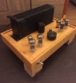
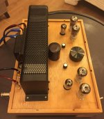
Finally finish my last build television vertical tube 10EW7 parallel amp with 6N2P for the tone stack, bamboo chassis. Just made all test and I am absolutely happy with the result, 6.7 watts x channel, separate power supply.
How it sound? Crispy, clear, sound stage incredible, open wide vocals, even at max volume where the scope reveal a clear distortion is very difficult to ear it.
I really push to the limit the second triode of the 10EW7 using the 10w plate dissipation to limit but the tube handle it very well, get just very hot but no other bad sign, now tested with all kind of music for several hours and I am really surprised by the quality of the sound...all the best to everybody
Attachments
Each time I'm convinced that this scheme works only with high plate resistance drivers i.e. pentodes, another schematic comes in to suggest triode drivers.
Yes, the triode does seem contradictory by the usual comments. If one looks at the output tube when it is turning on hard with lower Rp, the driver is turning off with higher Rp. So the N Fdbk becomes stronger when the output tube is stronger, helping out cancelling. This is amounting to 2nd harmonic cancellation with a triode driver. By selecting the driver operating current, one might be able to find a region where 2nd harmonic at the output gets nulled.
With the usual pentode driver, the driver load resistor keeps the N Fdbk more constant. But with the pentode driver one needs to linearize the Vin to Iout with a cathode resistor. By selecting a less than optimal (lower R) cathode resistor one can also get 2nd harmonic cancellation. Or with a high cathode resistor, one can avoid 2nd harmonic cancellation. Take your pick. Easier to find a high current pentode mainly.
----------------------
Cascode will certainly sub for a pentode, although why bother. Hmm, well with the high Z at the cascode top grid, one could put additional "local" N Fdbks (R attenuated) back to those. Would need to be crossed to get N Fdbks.
The differential part will help considerably to linearize the Vin to Iout of the driver, pentode or cascode.
Last edited:
Yes, sure for true "Schade"; is a potential divider local feedback.Shade shunt fb needs current drive, so either use a serial resistor on the anode side or on the cathode.
Either way needs higher voltage swing from the driver.
With triode driver without cathode degeneration, I interpret being a normal voltage feedback with potential divider, one arm being the triode rp. Since triode distorts (and all active devices distorts), including its rp, we have all efects that smoking-amp has mentioned.
Series resistor with triode driver will add a linear term to that, but essentially is different than pentode (CCS) driver.
Interesting will be to test the cascode option. Distorts different than pentode stage, so perhaps other form of compensation/interatcion with output stage is possible (if some benefit is possible)... or not
Yes, the triode does seem contradictory by the usual comments. If one looks at the output tube when it is turning on hard with lower Rp, the driver is turning off with higher Rp. So the N Fdbk becomes stronger when the output tube is stronger, helping out cancelling. This is amounting to 2nd harmonic cancellation with a triode driver. By selecting the driver operating current, one might be able to find a region where 2nd harmonic at the output gets nulled.
With the usual pentode driver, the driver load resistor keeps the N Fdbk more constant. But with the pentode driver one needs to linearize the Vin to Iout with a cathode resistor. By selecting a less than optimal (lower R) cathode resistor one can also get 2nd harmonic cancellation. Or with a high cathode resistor, one can avoid 2nd harmonic cancellation. Take your pick. Easier to find a high current pentode mainly.
----------------------
Cascode will certainly sub for a pentode, although why bother. Hmm, well with the high Z at the cascode top grid, one could put additional "local" N Fdbks (R attenuated) back to those. Would need to be crossed to get N Fdbks.
The differential part will help considerably to linearize the Vin to Iout of the driver, pentode or cascode.
Thanks! Actually, I need to find how to make this work for a double triode with high gm as LTP/driver with CCS tail. I believe I could test that during Christmas holidays.
Not TV tubes though. KT88 triode push pull, AC coupled to a 6n6p LTP with tail CCS. Zero global NFB. Plate to plate with 100k resistors didn't do anything. I wonder how the schematic at post #1154 works with 300k on 6FY7 plates... I had to go down to 47k to see a subtle effect on low frequency extension.
So, maybe this makes sense?
Yes, sure for true "Schade"; is a potential divider local feedback.
With triode driver without cathode degeneration, I interpret being a normal voltage feedback with potential divider, one arm being the triode rp. Since triode distorts (and all active devices distorts), including its rp, we have all efects that smoking-amp has mentioned.
Series resistor with triode driver will add a linear term to that, but essentially is different than pentode (CCS) driver.
Interesting will be to test the cascode option. Distorts different than pentode stage, so perhaps other form of compensation/interatcion with output stage is possible (if some benefit is possible)... or not
And since 6n6p rp is very low, so it has to be the feedback resistor too? But then becomes a heavy load.
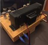
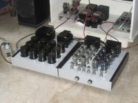
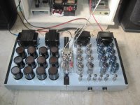
i have done a kt88 PPP triode mode many years ago.....with several of the kt88's in parallel, the combine plate resistance indeed becomes very low so that gnfb is not needed anymore...
Attachments
Last edited:
i have done a kt88 PPP triode mode many years ago.....with several of the kt88's in parallel, the combine plate resistance indeed becomes very low so that gnfb is not needed anymore...
Wow, what a beast.
Is this a real PPP (McIntosh style unity coupled) or what they nowdays call PPP?
Wow, what a beast.
Is this a real PPP (McIntosh style unity coupled) or what they nowdays call PPP?
PPP...no gnfb...not unity coupled, and yes from bob carver silver 7...
Erm, why? I'd not expect tubes' non-linearities to be cancelled just by paralleling severals of themi have done a kt88 PPP triode mode many years ago.....with several of the kt88's in parallel, the combine plate resistance indeed becomes very low so that gnfb is not needed anymore...
 .
.Best regards!
6KN6; still pretty cheap; also 42KN6. Kewl thing about these is no need to
bother with multiple secondary taps on OPT; those cathodes will handle the load.
(I bought out Antique's stock when they went on sale 20 years ago happy hunting)
There are 3 types:
1) The original Sylvania 'Doubles' These have 3 A fil current and match the pinout
on the tube data sheet.
2) Japanese Singles: Green stripe on bottom; 3A and 6KN6 pinout.
3) American Single Plate: These are actually 6KD6's; 36KD6; 2.75A fil current and
their pinout has the extra grid wires as on the 6KD6 pinout.
Erm, why? I'd not expect tubes' non-linearities to be cancelled just by paralleling severals of them
Best regards!
i know the issues paralleling tubes, if i had my way i would have just chosen a pair that can do the job and be done with it..
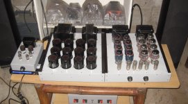
i am a fan of single pair of tubes to deliver power, like a pair of 4D32 for 120 watts, or a pair of QE08-200 for 300 watts....
but i was asked to work with the parts given to me, yes the owner game me all the parts and asked me, build me an amp out of all these parts...
and so build the amp i did...
there are other considerations, like if you triode wired a pentode, then plate resistance is lowered significantly, and getting then paralleled even more so...
and the biggest benefit that appeals to a lot of folks, you do not need gnfb at all, that i discovered in this amp build, while i did make a provision for that, after i heard the amp the first time, i knew i never had to connect the gnfb wire at all...
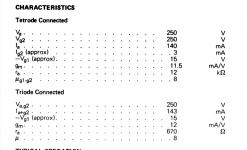
a look at the kt88 data sheets illustrated this...
Attachments
- Home
- Amplifiers
- Tubes / Valves
- Those Magnificent Television Tubes