I was thinking of using some television like tubes for a small guitar practice amp...
A zenith G615 modded to be a H615Z if I can do that then try to rewire the 12AT6 detector section as a kind of delayed AGC aka Compressor... as the 12AT6 is a dual diode triode.... then add a passive fender style tone stack ??? anyone have any ideas??? oh then when i get bored of playing tune into some classic AM rock... with the flip of a switch???
A zenith G615 modded to be a H615Z if I can do that then try to rewire the 12AT6 detector section as a kind of delayed AGC aka Compressor... as the 12AT6 is a dual diode triode.... then add a passive fender style tone stack ??? anyone have any ideas??? oh then when i get bored of playing tune into some classic AM rock... with the flip of a switch???
Been there; done that: Le Renard
The 6BQ6s, especially, make great audio finals, even though there is no mention of such use mentioned anywhere in the spec sheet. These sound as good as the 6V6, but can handle a lot more power, and some spec busting doesn't hurt at all, but improves the sonic performance.
The 6BQ7s also make excellent cascoded LTPs. This is another type that doesn't mention audio applications, and it does have some squirrelly plate characteristics (undocumented variable-u feature?) that makes it a bit more difficult to find a good audio load line. However, for this particular application, it works quite good.
How odd that you would build a tubed amp of essentially the same topology as one I did in Spring 2005. But for different reasons.
The lineup I used as follows- 6BQ7, 4BQ7, 6BQ7 & PP 6V6. The PS is SS & provides both +ve & -ve potentials. The 6V6s at times run AB2, but that is by intention.
I did not author an article for publication at the time since I got another contract to continue in the hitech field. But there was a discussion on RAT this past Spring covering the amp.
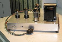
Photo attached if I can figure out how to run on this forum. First post.
You may have read some of my stuff in Glass Audio & AudioXpress.
Cheers to all, John L Stewart
Attachments
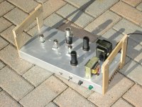
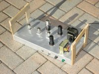
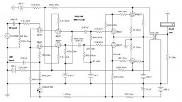
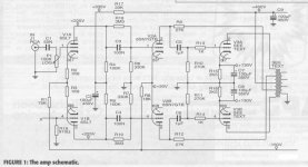
Here is the schema of the cascode amp I referred to yesterday. Notice the internal NFB to the upper cascode grids. That was one of the arrangments I wanted to try. Another was the AB2 connexion for the output section. This amp can deliver 26 watts at clipping when run on a regulated PS.
So lots of headroom while on a small PS as built. We don't normally run the program material at full power, so that the peaks can still run all out, even while powered by the small PS, another part of the experiment.
At 10W the THD is less than one %. I will post more tomorrow.
Cheers to all, John L Stewart
Attachments
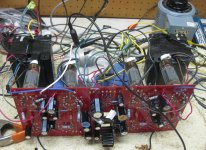
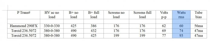
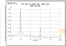
Now running 93 watts rms per channel both channels driven. Maryland Toroid PT and Hammond 1650T output trans.
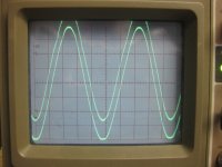
For results of today's experiments see attached pics.
These tubes don't redplate until I put over 80 ma or so quiescent current even with 425 volts on the plates. No redplating at all even when run 93 watts full power at 1000 Hz for several minutes at about 47 ma bias per tube.
For results of today's experiments see attached pics.
These tubes don't redplate until I put over 80 ma or so quiescent current even with 425 volts on the plates. No redplating at all even when run 93 watts full power at 1000 Hz for several minutes at about 47 ma bias per tube.
Attachments
How odd that you would build a tubed amp of essentially the same topology as one I did in Spring 2005. But for different reasons.
Yeah, that is an odd coincidence. When I did the Le Renard design, I found almost nothing on the 'Net about hollow state cascodes, even though it's quite common in solid state practice. About the only mention was for guitar amps, and then it was all about gain, and nothing about how this actually sounded.
It was just a case of try and listen, and hope it wasn't some sonic abomination. I figured cascoding just might help in the linearity dept, as it does for transistors, so I borrowed that from solid state practice.
The 6SN7-oids didn't have enough gain even as cascodes, and the 12AT7s lost too much gm too fast. So onto the RCA-30 for possible types. 6BQ7As and 6BK7Bs were intended for VHF cascode duty, and neither mentioned any audio applications. The 6BK7B turned out to be pretty hideous after trying some loadlines. The 6BQ7A, though its plate characteristic looks odd, showed good performance if you kept the VPK up, higher than usual for audio small signal triodes. You probably wouldn't like it in more conventional audio circuits, and there are better audio triodes for that. However, as a cascoded LTP (or a triode LTP) it turned out to work really well. It also has a u-factor that falls nicely between something like a 6FQ7 and a 12AT7, and with better linearity than the 12AV7.
You just have to watch out for those series connected heater 6BQ7s: they ring like bells. The parallel heater versions are quiet.
The lineup I used as follows- 6BQ7, 4BQ7, 6BQ7 & PP 6V6. The PS is SS & provides both +ve & -ve potentials. The 6V6s at times run AB2, but that is by intention.
Why? You get some extra benefit running the heater of the 4BQ7 out of spec as the upper cascode section?
Yeah, that is an odd coincidence. When I did the Le Renard design, I found almost nothing on the 'Net about hollow state cascodes, even though it's quite common in solid state practice. About the only mention was for guitar amps, and then it was all about gain, and nothing about how this actually sounded.
If you look into tube RF circuits you will find more cascode info. If not on the net, try looking at some old ARRL handbooks. I doubt anyone ever used them for audio back in the day, but they were common enough in RF apps.
It was just a case of try and listen, and hope it wasn't some sonic abomination. I figured cascoding just might help in the linearity dept, as it does for transistors, so I borrowed that from solid state practice.
The 6SN7-oids didn't have enough gain even as cascodes, and the 12AT7s lost too much gm too fast. So onto the RCA-30 for possible types. 6BQ7As and 6BK7Bs were intended for VHF cascode duty, and neither mentioned any audio applications. The 6BK7B turned out to be pretty hideous after trying some loadlines. The 6BQ7A, though its plate characteristic looks odd, showed good performance if you kept the VPK up, higher than usual for audio small signal triodes. You probably wouldn't like it in more conventional audio circuits, and there are better audio triodes for that. However, as a cascoded LTP (or a triode LTP) it turned out to work really well. It also has a u-factor that falls nicely between something like a 6FQ7 and a 12AT7, and with better linearity than the 12AV7.
I've recently done some 5751 cascode LTPs using a 6267 as a CCS. High gain, high linearity, and excellent balance. Most folks would balk at the voltage requirements though...
If you look into tube RF circuits you will find more cascode info. If not on the net, try looking at some old ARRL handbooks. I doubt anyone ever used them for audio back in the day, but they were common enough in RF apps.
That was the big problem: no mention of cascodes used as audio gain stages. After doing the Le Renard, I came across an example in the wild: the "Hedge" amp described in a 1956 edition of Wireless World. There are a few other examples of later designs that use audio cascodes here and there. (Ralph Karsten uses cascoded 6SN7s for the Atmasphere OTLs.)
I've recently done some 5751 cascode LTPs using a 6267 as a CCS. High gain, high linearity, and excellent balance. Most folks would balk at the voltage requirements though...
You have to trade off voltage output swing, but that's NBD when driving finals like the 6BQ6 and most of the audio pents. It'd become a problem if using triodes and pseudotriodes that need a lot more input swing. I did a SS active tail load: cascoded BJTs running on a negative rail. It's not used as often as it should be, given the performance.
Most folks would balk at the voltage requirements though...
Isn't this thread about TV tubes? The most popular TV tube is our friend the horizontal (line) output tube.....they like plenty of voltage too.
How odd that you would build a tubed amp of essentially the same topology as one I did in Spring 2005....... I found almost nothing on the 'Net about hollow state cascodes
As mentioned tube cascodes were used in RF. Common applications were TV and FM radio tuners and Tektronix scopes. The 6BQ7 was popular in TV and early Tek scopes. Tek later switched to the 6DJ8. The cascade was popular to approximate pentode operation with low capacitance triodes.
I also have a very similar amp design under construction using pentodes. The cross coupled local feedback goes to the driver tube screens. The cathode followers driving the output tubes are replaced with mosfets. Output tubes are TV sweep tubes.....not decided on which ones yet....or just which grids are being driven.
No, the fifty cent 13GB5!
They are on my short list. I want at least 100 WPC which the 13GB5's can easily do. I have 3300 ohm OPT's and the B+ will be in the 500 to 600 volt range.
Maryland Toroid PT
I forgot about that one. I got serial #001 way back when they cost $100. It was in an SSE until I stole the OPT's for another project. It's around here somewhere. It would need a small boost transformer to generate 600 volts.
You have to trade off voltage output swing, but that's NBD when driving finals like the 6BQ6 and most of the audio pents. It'd become a problem if using triodes and pseudotriodes that need a lot more input swing. I did a SS active tail load: cascoded BJTs running on a negative rail. It's not used as often as it should be, given the performance.
Isn't this thread about TV tubes? The most popular TV tube is our friend the horizontal (line) output tube.....they like plenty of voltage too.
I don't think folks would balk at the +V I used, which was 450V in this case. It was the requirement for a 150V negative rail due to the pentode CCS, even though it is trivial to generate if your main supply is a FWCT. The pentode CCS also requires a separate heater supply to maintain H-K voltage compliance. Most folks really don't like "complicated" power supplies it seems.....
Luckily, I scored two Maryland Toroid PT's, one new and one barely used each for the price of an Antek. However, the Antek's are unobtanium right now.
The other Maryland PT I want to do a 6L6GC AB2 amp. Unlike the Antek, the two 50 vac bias windings are symmetrically wired so I can make nice +- supplies for the mosfets using half wave doublers on each winding.
The other Maryland PT I want to do a 6L6GC AB2 amp. Unlike the Antek, the two 50 vac bias windings are symmetrically wired so I can make nice +- supplies for the mosfets using half wave doublers on each winding.
Luckily, I scored two Maryland Toroid PT's, one new and one barely used each for the price of an Antek. However, the Antek's are unobtanium right now.
Were they on Ebay? I saw a pair about a year ago. One was painted black maybe?
Unlike the Antek, the two 50 vac bias windings are symmetrically wired
I tried to explain that to John at Antek, but he didn't seem to understand what I was saying.
You can wire two 4TK400's together with the primaries out of phase to get 400-70-0-70-400. That is the ticket for something really big, but I am going for 100 to 150 WPC and the Maryland Toroid and a 160 VA isolation toroid looks like the ticket. I can get +/- 70 volts for bias and mosfet, +425 volts and +585 volts for B+
Were they on Ebay?
...Just about two weeks ago. Two were listed in separate auctions by the same seller. I was the only one that bid on the used one and nobody bid on the new one. We worked out a deal and by the time it was done they were each about the price of an Antek when you figure in shipping. Only then did I look up how much $$ they are from the factory now. Sit down before you look.
Would that be by having a separate full wave bridge on each winding and only using the CT as ground reference? And then using those two supplies to power separately each channel?You can wire two 4TK400's together with the primaries out of phase to get 400-70-0-70-400.
I wired the two secondaries on each transformer in parallel though they could be used independently, one winding on each transformer for each channel.
Connect the Blacks together on each transformer, and connect the Reds together on each transformer. Then connect the paralleled blacks on one transformer to the paralleled reds on the other transformer. Repeat with the other set of reds and blacks. Now the primaries are wired in parallel, but opposite phase. This is the key to getting the 70 volt windings out of phase for a FWB.
Connect the commons (white?)together (all 4 of them) and ground them.
Connect a full wave bridge with one 70 volt wire, or paralleled pair (grey?) from each transformer to the AC terminals on a bridge rectifier. Connect a filter cap from each DC terminal on the bridge to ground. You will get +95 volts from the + terminal and - 95 volts from the - terminal of the bridge.
Connect a full wave diode pair, or a tube rectifier, and a filter cap to ground, to the 400 volt wires from each transformer. You will get about 550 volts with a solid state rectifier.
Warning: Antek doesn't always wire two identical transformers identically. This is especially true with the red and black wires. There have been at least 3 different batches of AN4TK400's. One of them has a 5 volt rectifier winding instead of a 6.3 volt winding. It is wise to verify each winding with a voltmeter before hooking anything up to them. Anytime that you are wiring two transformers together ALWAYS test with a light bulb in series with the line voltage. That way the bulb lights up instead of the transformer if you get the phasing wrong.
I am 1200 miles away from my lab at the moment, so this is all from memory. I am not sure of the correct wire colors.
I worked out a way to make 400-330-70-0-70-330-400 VAC with two 4TK400's but I can't remember it right now.
I have seen what they go for now. I called when they first listed them on their web site....without a price, and asked about them. The lady admitted that they had never built any and told me it might take a while. I told her that I was developing a new tube amp design and looking for a high spec transformer option. The amp is now known as the SSE and the budget transformer option was the Allied 6K7VG then priced at about $45. She said that I could have the first one for $100 and the production versions would be slightly higher. It took several months for the transformer, but the list price would be around $200. Now almost $300. It did work very good, and I added it to the options list, but I don't think anyone ever bought any. I think the transformers you got might have been the ones that I saw on Ebay but I lost interest when the auction didn't meet the reserve.
Connect the Blacks together on each transformer, and connect the Reds together on each transformer. Then connect the paralleled blacks on one transformer to the paralleled reds on the other transformer. Repeat with the other set of reds and blacks. Now the primaries are wired in parallel, but opposite phase. This is the key to getting the 70 volt windings out of phase for a FWB.
Connect the commons (white?)together (all 4 of them) and ground them.
Connect a full wave bridge with one 70 volt wire, or paralleled pair (grey?) from each transformer to the AC terminals on a bridge rectifier. Connect a filter cap from each DC terminal on the bridge to ground. You will get +95 volts from the + terminal and - 95 volts from the - terminal of the bridge.
Connect a full wave diode pair, or a tube rectifier, and a filter cap to ground, to the 400 volt wires from each transformer. You will get about 550 volts with a solid state rectifier.
Warning: Antek doesn't always wire two identical transformers identically. This is especially true with the red and black wires. There have been at least 3 different batches of AN4TK400's. One of them has a 5 volt rectifier winding instead of a 6.3 volt winding. It is wise to verify each winding with a voltmeter before hooking anything up to them. Anytime that you are wiring two transformers together ALWAYS test with a light bulb in series with the line voltage. That way the bulb lights up instead of the transformer if you get the phasing wrong.
I am 1200 miles away from my lab at the moment, so this is all from memory. I am not sure of the correct wire colors.
I worked out a way to make 400-330-70-0-70-330-400 VAC with two 4TK400's but I can't remember it right now.
Only then did I look up how much $$ they are from the factory now. Sit down before you look.
I have seen what they go for now. I called when they first listed them on their web site....without a price, and asked about them. The lady admitted that they had never built any and told me it might take a while. I told her that I was developing a new tube amp design and looking for a high spec transformer option. The amp is now known as the SSE and the budget transformer option was the Allied 6K7VG then priced at about $45. She said that I could have the first one for $100 and the production versions would be slightly higher. It took several months for the transformer, but the list price would be around $200. Now almost $300. It did work very good, and I added it to the options list, but I don't think anyone ever bought any. I think the transformers you got might have been the ones that I saw on Ebay but I lost interest when the auction didn't meet the reserve.
Last edited:
I just built a screen drive amp because I several pairs of 6L6GC output transformers, pentode mode transformers. I used the 6DQ6B (6GW6) because it so similar to the 6L6GC. The amp sounds fantastic.
I noticed that many individuals building screen drive amps are of the opinion that the screen drive circuit needs to source a healthy amount of current. I disagree with the notion and took a different direction with the drive circuit. I based this on the success I had making an ultralinear GU-50 which, according one poster on one of these forums, is impossible because of the low screen voltage of the GU50 (not unlike these TV tubes). For that build, I downloaded the German datasheets and spent several hours translating them. Somewhere in the MANY pages of data for that particular tube, there is mention of using 5 Kohm resistors on the screens and being able to increase the screen voltage. I do not recall exactly how much resistance I used on the screens for my GU50 ultralinear amp, but I do believe I used about double that. I wanted to keep the screen voltage down far enough below plate voltage so that the electrons would pass right on through the screen grid and head for the plate. I measured the voltage and, while it was over 300, it wasn't too much over 300, and the amp has been running for months, and I tend to leave it on most of the day, listening to music about 16 hours a day as I work from home. So, I'm satisfied regarding reliability of the design, and the sound quality is just phenomenal, so I'm satisfied regarding the design.
I believe that the screen merely needs to present a POTENTIAL and doesn't necessarily have to pass current. First time I built a push-pull-parallel ultralinear amp, I HAD to use screen grid resistors; without them the amp sounded horrible. On this particular build, I have 5 Kohm resistors on the screens and it sounds wonderful.
This was a very easy build. I do believe I am going to get more of these tubes since they are so cheap and make a few more since I have so many transformers lying about.
GU-50 typically runs the g2 at around 200 to 250 V, while TV sweeps usually run g2 around 150 V, so I would not call GU-50 a low g2 voltage tube. It obviously is not a particularly high g2 V tube either like 6L6GC at 450 V.
The 6DQ6B you have chosen is a particularly low g2 current tube at 1.8 mA/65 mA or 1/36 ratio. So is not a good example to generalize about g2 drive current requirements. Some Sweep tubes will draw plenty of g2 current. The higher the Zpri of the OT, the less the g2 current will be also, since it is just a fixed fraction of the max plate current.
6DQ6B is the same tube (except pinout) as 6JN6, 6GE5, 6GV5, 6JM6, 6FW5. These tubes have all been phenomenally successful in Pete Millett's DCPP Engineers Amp. (and the tube supply nearly wiped out) Likely any amplifier made using these tubes is going to sound good. A larger tube that also worked wonders in the DCPP was the 6HJ5 at 24 W diss, but its supply has similarly been evaporated.
The 6GW6 similarly has a group of identical tubes: 6GT5, 6GJ5, 6JT6, 6JB6
At least one of these has been tried in the DCPP, that I know of, with good results.
Last edited:
Yeah, that is an odd coincidence. When I did the Le Renard design, I found almost nothing on the 'Net about hollow state cascodes, even though it's quite common in solid state practice. About the only mention was for guitar amps, and then it was all about gain, and nothing about how this actually sounded.
It was just a case of try and listen, and hope it wasn't some sonic abomination. I figured cascoding just might help in the linearity dept, as it does for transistors, so I borrowed that from solid state practice.
The 6SN7-oids didn't have enough gain even as cascodes, and the 12AT7s lost too much gm too fast. So onto the RCA-30 for possible types. 6BQ7As and 6BK7Bs were intended for VHF cascode duty, and neither mentioned any audio applications. The 6BK7B turned out to be pretty hideous after trying some loadlines. The 6BQ7A, though its plate characteristic looks odd, showed good performance if you kept the VPK up, higher than usual for audio small signal triodes. You probably wouldn't like it in more conventional audio circuits, and there are better audio triodes for that. However, as a cascoded LTP (or a triode LTP) it turned out to work really well. It also has a u-factor that falls nicely between something like a 6FQ7 and a 12AT7, and with better linearity than the 12AV7.
You just have to watch out for those series connected heater 6BQ7s: they ring like bells. The parallel heater versions are quiet.
Why? You get some extra benefit running the heater of the 4BQ7 out of spec as the upper cascode section?
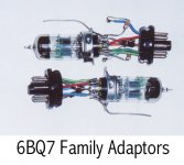
The 4BQ7 serves a specific purpose. Its heater runs on the 5V winding of the PT, so there are no problems with H-K insulation.
I don’t worry much about which tube or that may ‘sound’ better. IMO, an amplifier should & can be a piece of wire with gain. Any imperfection will be reduced provided it is inside a stable NFB loop. Microphonics are a problem that can be avoided. But they may add to the sound of a rock musicians performance!
Some professional musicians could detect differences, as they look for a particular sound. And perhaps some repair techs who can hear a difference in various amplifiers since they experience so many of them, most on the same speaker(s) & in the same room.
Not so the ordinary person. So it becomes a subjective observation, not easily repeatable by others who will have different speakers, baffles, listening rooms & on & on. I depend pretty much on objective measurements that are repeatable by others in order to gage an amplifiers performance. If an amp sounds drastically different, the problem might be traced to its inability to drive a particular speaker or perhaps some internal failure.
In my case, now at 81 years my left ear is shot. So I can’t depend on that.
Many of the home built projects I’ve seen looked great on the table with their carefully polished wood frames. But underneath was something else. A rats nest of wire & poorly soldered connexions. Many probably created some smoke before any sound. Some appear as tho they were built before the terminal strip was invented.
A while back in one of my projects I did objective A vs B tests on the ‘BQ7 family when compared to the rather expensive 6SL7 / 6SN7 family. The THD & IMD results would surprise many! But I didn’t have any problem with microphonic ‘BQ7s.
All my opinions, anyway.
And attached is something on another trick circuit I did quite a few years ago while still on the road for R&S. All my recent (20 years) has been experimental. This one published in Glass Audio May & June 1999.
The schema demonstrates an easy way to get the large drive required for low mu triodes. The 6080 was used in some early TV so I guess the cct qualifies to be here.
Cheers to all, John L Stewart
Attachments
Bootstrapped 6SN7 driver plate loads. I would guess those UL taps are providing more voltage swing than required however, giving some positive Fdbk.
It might be interesting to replace the 6SN7 drivers with some pentodes, using the same cross UL bootstrapped plate load idea. But add UL tap Neg. feedbacks to the driver g2's as well to provide some local Neg. Fdbk. A UL driver stage if you will. Likely have to use some R dividers to attenuate the Neg Fdbks and reduce the DC voltage for the driver screens.
It might be interesting to replace the 6SN7 drivers with some pentodes, using the same cross UL bootstrapped plate load idea. But add UL tap Neg. feedbacks to the driver g2's as well to provide some local Neg. Fdbk. A UL driver stage if you will. Likely have to use some R dividers to attenuate the Neg Fdbks and reduce the DC voltage for the driver screens.
Last edited:
GU-50 typically runs the g2 at around 200 to 250 V, while TV sweeps usually run g2 around 150 V, so I would not call GU-50 a low g2 voltage tube. It obviously is not a particularly high g2 V tube either like 6L6GC at 450 V.
The 6DQ6B you have chosen is a particularly low g2 current tube at 1.8 mA/65 mA or 1/36 ratio. So is not a good example to generalize about g2 drive current requirements. Some Sweep tubes will draw plenty of g2 current. The higher the Zpri of the OT, the less the g2 current will be also, since it is just a fixed fraction of the max plate current.
6DQ6B is the same tube (except pinout) as 6JN6, 6GE5, 6GV5, 6JM6, 6FW5. These tubes have all been phenomenally successful in Pete Millett's DCPP Engineers Amp. (and the tube supply nearly wiped out) Likely any amplifier made using these tubes is going to sound good. A larger tube that also worked wonders in the DCPP was the 6HJ5 at 24 W diss, but its supply has similarly been evaporated.
The 6GW6 similarly has a group of identical tubes: 6GT5, 6GJ5, 6JT6, 6JB6
At least one of these has been tried in the DCPP, that I know of, with good results.
My point was simply that I have thus far proven to my satisfaction that the purpose of the screen is not to source current (or absorb current) but to provide a potential. I can be easily persuaded I am wrong if someone can show me conclusive test results proving otherwise. Many amp builders (of typical PP amps) are convinced the amp sounds better if screen resistors are used. In other words, just because the screen CAN source (or absorb) current doesn't mean it has to for sound quality. It's purpose is to present a voltage potential greater than G1 but less than the plate. What is the screen but another control grid? We don't want current flowing through the control grid, it's held negative in relation to the cathode, negligible current flow, and we consider that ideal. Why should the screen be different? The screen is just a bigger version of the control grid
- Home
- Amplifiers
- Tubes / Valves
- Those Magnificent Television Tubes