Hi all,
I have a simple circuit and have tried to mod it for EM80s rather than the EM87(6e2) it was designed for, but am doing something wrong.
Can anyone suggest the best way to mod this schematic. It's a simple vu meter circuit, and before anyone bemoans me for copyright, I purchased the PCBs and have the right to use the circuit

Appreciate the help


I have a simple circuit and have tried to mod it for EM80s rather than the EM87(6e2) it was designed for, but am doing something wrong.
Can anyone suggest the best way to mod this schematic. It's a simple vu meter circuit, and before anyone bemoans me for copyright, I purchased the PCBs and have the right to use the circuit
Appreciate the help
.............EM87 EM80
input grid....1.....1 same
filament.....4,5..4,5 same
cathode.....3.....2 move cathode from 3 to 2
triode A.....9.....7 move anode from 9 to 7
target.......6.....9 move target fom 6 to 9
W2 should be set to about 500K. You want no more than 250VDC on the target, optimal 200VDC.
With more signal, the negative voltage on the grid goes up. The more negative voltage, the more positive pin 7 becomes, and the display widens. Pin 7 should have about 50-70 VDC with a narrow display. On EM80 pins 3, 6, and 8 aren't used.
I should have also said that varying the B+ will change sensitivity, which will change how much negative voltage on grid you'll need.
Also it's best to keep the target as low as possible and still see the display, somewhere between 175 and 220. Too high voltage on the target will decrease the life of the tube. Most display or eye tubes only have a 1000hr life.
Also it's best to keep the target as low as possible and still see the display, somewhere between 175 and 220. Too high voltage on the target will decrease the life of the tube. Most display or eye tubes only have a 1000hr life.
.............EM87 EM80
input grid....1.....1 same
filament.....4,5..4,5 same
cathode.....3.....2 move cathode from 3 to 2
triode A.....9.....7 move anode from 9 to 7
target.......6.....9 move target fom 6 to 9
W2 should be set to about 500K. You want no more than 250VDC on the target, optimal 200VDC.
OK, I'm going to admit something now. I am pretty good with electronics, but sometimes I'm tired and make mistakes.
I knew I had the wiring right a few evenings ago, but I could not get the tube to light. Hence this post to make sure I wasn't going mad.
So I took another look this morning armed with the info above from DeathRex. Nope it still wouldn't work!

Then I made up a test circuit just to be sure I wasn't mad, and tube wasn't kaput. It worked fine.
I went back to the PCB, and then it dawned on me. I traced the earth/ground for the cathode and noted it just stopped and wasn't actually grounded. Hmm I thought this sucks as a PCB. Then, and only then, did I notice the missing links I should have soldered onto the board! What a dumb f**k!
Attached is the PCB image so you can see what a c*ck I was
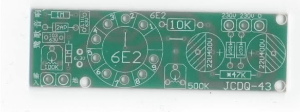
Just though this would make you all smile. Now to build a small amp circuit to drive the input with, as it needs about 10v peak to peak to make the eye close fully.
I also note that W2 can be omitted and replaced with a fixed 500K resistor as this sets the idle position on the eye perfectly. I also omitted R1 as this improved the rise/fall of the EM80.
Happy Easter
- Status
- This old topic is closed. If you want to reopen this topic, contact a moderator using the "Report Post" button.
- Home
- Amplifiers
- Tubes / Valves
- Suggested Circuit Changes to use EM80 in place of 6E2 Eye