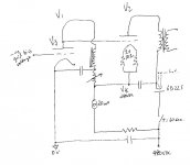
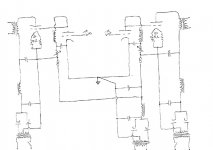
I'm using something similar at the moment exception being that the B supply for the driver is seperate. The issue that I have with this is that as the line voltage varies, so does the bias voltage for the output stage. I could regulate the driver supply, that would work, but I have this idea... (circuit attached).. run the whole thing from a single supply. I can see that Vk is set now by Vg (driver plate) which in-turn is set by the -ve bias at the grid of the driver and is independant of line voltage fluctuations. I am very interested in any comments and/or opinions, but mostly whether you can stack a supply upon itself like this. I simply dont know and I'd just go ahead and build it.. but I really want to know if it should fly first.
*edit* switch is 3ph contactor rated at 600vAC/65A, hope it will be ok with contacts wired in parallel for the app. Timer is in the coil cct.
Thank you for your interest.
*edit* switch is 3ph contactor rated at 600vAC/65A, hope it will be ok with contacts wired in parallel for the app. Timer is in the coil cct.
Thank you for your interest.
Attachments
Last edited:
Hi Ceglar,
That's funny, I got almost the same idea a few weeks ago for a PP amp with two power supplies.
Regarding your circuit, I dont think it will work if you run it this way. Firstly the grid of V1 has to be on a negative potential which means you will have to place a C before it (I'm guessing you dont want to have any C's in the signal path). Secondly the current for V2's cathode will flow through the driver stage. Not only is this not recommended, but it will also change the bias point of V2. Thirdly; what is the purpose for the 6D22S? You already have a delay switch in place...
In my oppinion using two power supplies should work if you change your circuit aswell. If you want a fully DC coupled SE amp with only one power supply, and you are willing to drop the DHT tube, look for screen drive. Certain tubes perform really well with screen drive (screen drive = applying the signal to the screen grid (g2) of a tetrode / pentode).
Do you have the ability to simulate your idea's with an application like spice?
Regards,
Anthonie
Anthonie, thanks.
V1 bias is set from the plate of a DC input stage, so no capacitor is required. The purpose of the diode is a soft ramp up of voltage to the output stage anode, something that a hard switch cannot facilitate. Now, yes.. I see it.. you're right.. V2 current has no choice but to make its was to/from ground via V1. Thanks, you saved a 71A triode and I'm back to the drawing board.
V1 bias is set from the plate of a DC input stage, so no capacitor is required. The purpose of the diode is a soft ramp up of voltage to the output stage anode, something that a hard switch cannot facilitate. Now, yes.. I see it.. you're right.. V2 current has no choice but to make its was to/from ground via V1. Thanks, you saved a 71A triode and I'm back to the drawing board.
Anthonie, thanks.
V1 bias is set from the plate of a DC input stage, so no capacitor is required. The purpose of the diode is a soft ramp up of voltage to the output stage anode, something that a hard switch cannot facilitate. Now, yes.. I see it.. you're right.. V2 current has no choice but to make its was to/from ground via V1. Thanks, you saved a 71A triode and I'm back to the drawing board.
If you warm up the 6D22S together with the other tubes, the 6D22S will only act as a fancy resistor of about 85 ohms.
Are you fixed at using these tubes, or are other tubes allowed as well?
Anthonie, thanks.
In practice, 6D22S pair as a FW rectifier.. seperately heated and in heated state then with time delay to the primary of the main B supply transformer, voltage ramps up quite obviously on an analog volt meter, from 0 to several hundred volts t= >10 seconds and smoothly.
Fixed with the tubes, yeah.. I have enough of the type on hand, and enough success with them so far.. just looking to push forward, I need time to think but it seems that the DC current path will force me to use a seperate driver suppy.. as you have pointed out, that output stage current need to go some where.
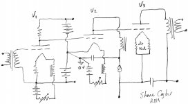
I have a three stage DC DHT amp that works, see attached.
In practice, 6D22S pair as a FW rectifier.. seperately heated and in heated state then with time delay to the primary of the main B supply transformer, voltage ramps up quite obviously on an analog volt meter, from 0 to several hundred volts t= >10 seconds and smoothly.
Fixed with the tubes, yeah.. I have enough of the type on hand, and enough success with them so far.. just looking to push forward, I need time to think but it seems that the DC current path will force me to use a seperate driver suppy.. as you have pointed out, that output stage current need to go some where.
I have a three stage DC DHT amp that works, see attached.
Attachments
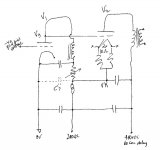
Seems theres no obvious way for me getting around the need for two B supplies.
At least the bias of V2 will remain constant with line voltage fluctuations, which was the main problem with the 3 stage circuit posted, and I'm thinking that the rheostat wont be in the AC signal loop of V1, which is good.
Its a start anyway..
At least the bias of V2 will remain constant with line voltage fluctuations, which was the main problem with the 3 stage circuit posted, and I'm thinking that the rheostat wont be in the AC signal loop of V1, which is good.
Its a start anyway..
Attachments
or do you want it in SE?
and what tubes you want to use.
SE as per the schematic and 71A drive 2A3 or 300B for example.
What I was wanting is to run both stages from a single supply. Its a 2 channel amplifier and the high B supply transformer has dual secondaries, the low B supply transformer has just a single secondary.. the way it was had the filaments of V2 effectively connected together a the point where the high B stacks onto the low B. It works, but I dont know how compromised that is.
If you can think of a way to run it from a single supply, I'd try it.
Closest I can get is with the last circuit (3) the filter CCS moves back to the supply side of where the two supplies connect and looks like it will isolate the two channels completely despite using a common low B supply, still the filament return of V1 are connected together and I'm not sure if that should matter or not.
Any comment is welcome.
Interesting circuit that you posted BTW.. any idea who designed it, I didnt see that detail.
Attachments
or do you want it in SE?
and what tubes you want to use.
I've just picked it up.. the PS in the schematic you posted. YES that is exactly what I am looking for.
Thank you!
- Status
- This old topic is closed. If you want to reopen this topic, contact a moderator using the "Report Post" button.
- Home
- Amplifiers
- Tubes / Valves
- Will this 2 stage DC DHT cct idea work?