Its very simple. I did it this way... I removed the 1/4" jack. I took the transformer CT wires to ground. I removed the wire that connected the two output tubes on pin number 8. I installed a 10 ohm 1watt resistor from pin 8 of each output tubes to ground.
I found the two grid resistors connection at the center terminal of the bias pot and removed the left resistor from the center connection of the pot and soldered a wire onto it. I installed another pot where the 1/4" jack was. I soldered the grid resistor wire to the center connection (the out of the pot). I soldered a cap from the center terminal of the pot that was added to ground. (Just like the other side) I paralleled the ground terminal of the original pot to the pot I added. I paralleled a wire from the in connection of the original pot to the pot I added. Note* Looking at the back of the pot as it is installed in the chassis is on the left ground, center is out, right terminal is in.
Now I added 3 turret terminal test points to the chassis. One black goes to power supply ground. One red goes to the #8 pin of one of the output tubes socket. The other red test point is connected to the number 8 pin of the other output tube.
I changed my bias circuit as follows I removed the resistor (10K) that is connected to the bias diode and replaced it with a 1K resistor. I replaced the original bias cap (60mfd/150vdc) with a 100/150vdc and I replaced the cap 220/63 with 100/100
Attachments
Last edited:
If you change the grid resistors so that you can run most of the 8417's out there the amp will bias up and run fine with what ever you choose to put in it output tube wise. I run 6550's at about 40mA a tube. I run KT88's a lot hotter. If I were you I would put the 8417 back on the shelf and let them sit.
PM me if you have any questions.
PM me if you have any questions.
Sorry to resurrect this from the dead, but now the kids are out of the house, I'm dusting off my old 8417 Quicksilvers and dread the thought of what might happen if/when the 8417's finally go.
So my question here is (and excuse my tube ignorance) if I do this dual bias mod, does that mean I no longer have to use match pairs for the output tubes?
(BTW: I'll also probably follow the mods to swap to 6550/KT88s come the inevitable death of the 8417s)
UPDATE: Ahh, I answered my own question when I found this post right after I posted this: https://www.diyaudio.com/forums/tubes-valves/107403-quicksilver-8417-biasing.html#post1285701. Thanks @Burnedfingers!
Last edited:
OK, resurrecting again... ")
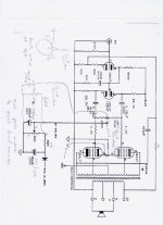
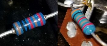
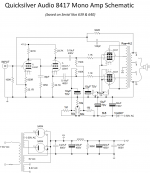
I traced out the circuit of my pair of Quicksilvers prior to making the mods discussed above (and elsewhere) and found differences from the other versions I found on the net, incl the one above - both in component count and values. So I re-created the schematic in Visio for anyone interested. However, I'm stumped on the values of the bias circuit resistor values. I tried measuring, but the caps screw up the resistance measurements, and I cannot tell which direction to read the color bars to determine the marked resistance!
Attached is the schematic so far (questioned values in red) and pics of the two resistors in question.
Any help welcome.
Attachments
Last edited:
Kinda has to be like this.
Bias for the 8417 is liable to be 45V, say 60V to 35V.
You MUST have a large stopper on the ground end of the bias pot so you can't turn to zero and burn-up irreplaceable 8417s.
Since the 50VAC makes 70V DC, the resistor at the hot end must be small to ensure enough bias for "hot" 8417s.
Verify you get roughly 60V-35V BEFORE you put the 8417s in. Start at the most negative bias and dial-up cautiously.
Attachments
Thank you for your replies. They forced me to get off my a** and plug one of the amps in (no tubes) and measure the voltages at the bias resistor points - see pic.
Interestingly, the bias voltages are much lower than your assumptions @PRR, with the actual bias voltage set at ~23volts - from last time they were operational.
Given the voltage-drop measurements, I'd have to assume the resistances are actually 10K, 10K(pot) and 30K as @Alllensoncanon suggested.
This *is* definitely surprising though, since it also somewhat conflicts with @Burnedfingers dual bias circuit, which implies a much larger 'hot' range.
UPDATE: I was just reading that, indeed, 8417s require a much lower bias voltage (in the order of -20V) than others octals such as 6550 (~-40V). I assume that is why the difference with Burnedfingers circuit (and now Ketje's) which would also work with replacement tubes such as the 6550/KT88s
Attachments
Last edited:
My 2 cents
Mona
Hi, Mona, I didn't see your reply before I posted. So you have interesting differences with Burnedfingers' dual bias circuit. I have a couple of questions if you don't mind:
1) Why the much lower value wiper capacitors than the original design?
2) Why add the 1M wiper resistors?
3) Most important: Why did you join pins 1 & 8 on the output tubes?
Waiting in Antici....pation
Thanks.
1) First i don't like useless fat cap's and smaller cap's means less leaking current.
2) When the wiper loses contact the grid is floating, no good, the 1M prevents this.
3) In a KT88 the cathode is internaly conneted to the g3 (dp) and pin 1 is N.C.
But tubes like the EL34 have the g3 on pin 1, with 1 & 8(cathode) together is allways ok.
Mona
2) When the wiper loses contact the grid is floating, no good, the 1M prevents this.
3) In a KT88 the cathode is internaly conneted to the g3 (dp) and pin 1 is N.C.
But tubes like the EL34 have the g3 on pin 1, with 1 & 8(cathode) together is allways ok.
Mona
Take a look here at yet another bias Modification.http://www.triodeel.com/8417.htm
...the bias voltages are much lower than your assumptions @PRR, .... reading that, indeed, 8417s require a much lower bias voltage (in the order of -20V) than others octals such as 6550 (~-40V).....
Vast apologies!!!
I know the 8417 well (had an array of twenty at one time) and *forgot* that its Mu(g2) is higher than most.
(I'm having medical issues and am not thinking straight.)
Someone who can do voltage-divider math clearly should be able to work this out.
(In my defense: if you had blindly followed my plan, nothing would burn-up, just run cold, and "hoarse" on small signals.)
Heheh. PRR, after I posted my "indeed, 8417s require a much lower bias voltage" update, I went back and noticed that where I saw that info was actually in one of your posts!
As for the voltage divider math, that's what I used to determine the correct stock OEM resistor values once I'd measured the voltages.
Thank you for your replies and posts!
As for the voltage divider math, that's what I used to determine the correct stock OEM resistor values once I'd measured the voltages.
Thank you for your replies and posts!
Last edited:
To complete this for posterity, I'm attaching both the updated/corrected original circuit for my amps, as well as the dual-bias modified circuit. For the latter I've made a bit of an amalgam of both Burnedfingers' and Ketje's circuits, though I may reduce the bias capacitor values depending on space. Also using a stereo 1/4 jack for the test points to save extra holes, and I'll use 10-turn pots to avoid needing to be too careful with trimming - given the new much wider range of voltage.
One final question, can anyone tell me the wattage requirements for the 23K2 resistors on top and bottom of the 12AU7 splitter - I'm not sure how much current flows through that circuit? One of my resistors is showing strange resistance readings and I think it may be on it's way out (or already out) but I can't find any replacements at Mouser/Digikey/Arrow/Jameco of that resistance or near, that are more than 5W. I'm worried that may not be enough?
Thanks
Attachments

- Status
- This old topic is closed. If you want to reopen this topic, contact a moderator using the "Report Post" button.
- Home
- Amplifiers
- Tubes / Valves
- Quicksilver 8417 Bias