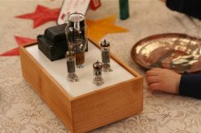
I recently finished building an RH84 amp and thought I would share my experience.
First off, the amp sounds great. Thanks to Alex for the great design, and thanks to everyone else for their posts about their builds. I am very pleased that the amp sounded so good straight away and didn’t require any tweaking or rework. Well, there was one little hiccup …
The amp started life as an old Dumont console that my neighbor was throwing away. I asked for it, and he was happy to give it away. After I striped the amp from the console, I powered it up. It worked, though intermittently, and one of the output tubes started glowing. I recapped it, but only one channel worked. I wasn’t sure if it was a bad tube, but thought it was most likely a bad connection. There was corrosion on some of the solder joints and they looked pretty bad.
After looking around on the web, I decided to reuse the iron and output tubes to build an RH84.
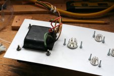
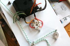
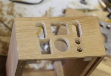
I started out cutting and drilling the cassis. After that, I mounted the tube sockets and power supply transformer. Then I wired up the heaters and HV windings.
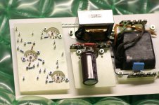
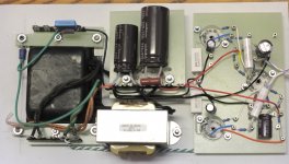
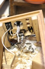
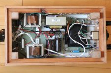
It took me a long time to figure out how to lay out the power supply. I spent a day trying to figure out how to mount the PS caps vertically and what to do with the choke. Finally it hit me that night. Just mount the choke on one side, and then mount the caps on the other. Run a terminal strip down the middle to solder the parts to. As it is, there is just a short wire running straight up from the rectifier socket to the first filter cap. The other end of the cap is soldered to the end terminal – right in front of the power transformer. My goal was to make the power supply compact and only have short lead lengths for any AC voltages.
One thing I thought turned out well was to use two PCB strips that run on either side of the power transformer. I mounted a terminal strip on each one. One side has the ground connections with a cap and resistor to isolate the circuit ground from the earth ground. The other side has the heater connection and the AC power connection.
I designed a turret board in Eagle and then used the instructions from TubeDepot for mounting the turrets. I have seen some amazing amps, and had hoped that by using a turret board, this amp would be very clean and orderly. It started out looking great, but the more parts I added, the messier it became. I also ran into some problems with parts being too close to the edge of the board. Don’t know if I will go this route again.
When I soldered up my last amp, I ran into a problem with the turrets. About half of them were contaminated with something, and would not take solder. The solder would not flow on the turrets, instead it would just bead up like you were soldering glass. This was incredibly frustrating and I never did find a solution. It seemed that when you hit the bad turrets with a soldering iron, they would turn a sort of glossy black. I tried cleaning and polishing them, but it never worked.
I prepared for the same results on this board by only wrapping leads and wires around the terminals, and never mounting parts in the top hole. I figured that way, even if the solder didn't stick to the turret, it would still stick between the wires that were wound on it. Luckily almost all of these turrets were good (these were from a different supplier, though same manufacturer - Keystone). I did end up with a couple where the solder didn't flow well, but it was not nearly as bad as last time.
I used 20 AWG solid wire for most connections. It was much better then the 18 AWG stranded wire I used for my last build.
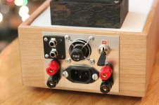
After I built the case and laid out the rear panel, I realized I had forgotten to include the fuse holder. Oops. I ended up mounting it in the center of the vent hole. It almost looks like I planned it that way.
The one hiccup I had was due to one of the donor output transformers. It had an extra winding that was used as a filter in the original power supply. I clipped the wire but didn’t dress the end. Apparently there was enough metal sticking out on the end to make contact with an unsuspecting grid resistor. On power up, there were some fancy blue sparks in the 12AT7 and a curl of smoke out of the vent hole. The grid and plate resistors were toast, as well as half the 12AT7. After I replaced the tube and resistors, it worked like a champ.
I gave the amp to my brother-in-law for Christmas. He is using it with some low efficiency 3-way speakers, but it sounds great and has enough power for his large bedroom. I also played the amp at a friend’s house. He is the person who first got me interested in tube audio. I helped him a bit when he was building his Bottlehead setup. We didn’t do any A/B testing, but he was content to listen to this amp all afternoon. His comments about the RH84 were very favorable. I think the main difference was that the RH84 had enough power, while the Bottlehead was underpowered for his speakers. I think it was an eye-opener for him.
I am very pleased with the amp and highly recommend it.
First off, the amp sounds great. Thanks to Alex for the great design, and thanks to everyone else for their posts about their builds. I am very pleased that the amp sounded so good straight away and didn’t require any tweaking or rework. Well, there was one little hiccup …
The amp started life as an old Dumont console that my neighbor was throwing away. I asked for it, and he was happy to give it away. After I striped the amp from the console, I powered it up. It worked, though intermittently, and one of the output tubes started glowing. I recapped it, but only one channel worked. I wasn’t sure if it was a bad tube, but thought it was most likely a bad connection. There was corrosion on some of the solder joints and they looked pretty bad.
After looking around on the web, I decided to reuse the iron and output tubes to build an RH84.
I started out cutting and drilling the cassis. After that, I mounted the tube sockets and power supply transformer. Then I wired up the heaters and HV windings.
It took me a long time to figure out how to lay out the power supply. I spent a day trying to figure out how to mount the PS caps vertically and what to do with the choke. Finally it hit me that night. Just mount the choke on one side, and then mount the caps on the other. Run a terminal strip down the middle to solder the parts to. As it is, there is just a short wire running straight up from the rectifier socket to the first filter cap. The other end of the cap is soldered to the end terminal – right in front of the power transformer. My goal was to make the power supply compact and only have short lead lengths for any AC voltages.
One thing I thought turned out well was to use two PCB strips that run on either side of the power transformer. I mounted a terminal strip on each one. One side has the ground connections with a cap and resistor to isolate the circuit ground from the earth ground. The other side has the heater connection and the AC power connection.
I designed a turret board in Eagle and then used the instructions from TubeDepot for mounting the turrets. I have seen some amazing amps, and had hoped that by using a turret board, this amp would be very clean and orderly. It started out looking great, but the more parts I added, the messier it became. I also ran into some problems with parts being too close to the edge of the board. Don’t know if I will go this route again.
When I soldered up my last amp, I ran into a problem with the turrets. About half of them were contaminated with something, and would not take solder. The solder would not flow on the turrets, instead it would just bead up like you were soldering glass. This was incredibly frustrating and I never did find a solution. It seemed that when you hit the bad turrets with a soldering iron, they would turn a sort of glossy black. I tried cleaning and polishing them, but it never worked.
I prepared for the same results on this board by only wrapping leads and wires around the terminals, and never mounting parts in the top hole. I figured that way, even if the solder didn't stick to the turret, it would still stick between the wires that were wound on it. Luckily almost all of these turrets were good (these were from a different supplier, though same manufacturer - Keystone). I did end up with a couple where the solder didn't flow well, but it was not nearly as bad as last time.
I used 20 AWG solid wire for most connections. It was much better then the 18 AWG stranded wire I used for my last build.
After I built the case and laid out the rear panel, I realized I had forgotten to include the fuse holder. Oops. I ended up mounting it in the center of the vent hole. It almost looks like I planned it that way.
The one hiccup I had was due to one of the donor output transformers. It had an extra winding that was used as a filter in the original power supply. I clipped the wire but didn’t dress the end. Apparently there was enough metal sticking out on the end to make contact with an unsuspecting grid resistor. On power up, there were some fancy blue sparks in the 12AT7 and a curl of smoke out of the vent hole. The grid and plate resistors were toast, as well as half the 12AT7. After I replaced the tube and resistors, it worked like a champ.
I gave the amp to my brother-in-law for Christmas. He is using it with some low efficiency 3-way speakers, but it sounds great and has enough power for his large bedroom. I also played the amp at a friend’s house. He is the person who first got me interested in tube audio. I helped him a bit when he was building his Bottlehead setup. We didn’t do any A/B testing, but he was content to listen to this amp all afternoon. His comments about the RH84 were very favorable. I think the main difference was that the RH84 had enough power, while the Bottlehead was underpowered for his speakers. I think it was an eye-opener for him.
I am very pleased with the amp and highly recommend it.
Attachments
-
 RH84_1.jpg240.2 KB · Views: 262
 -
 RH84_2_1907.jpg274.1 KB · Views: 256
 -
 RH84_3.jpg273.7 KB · Views: 250
 -
 RH84_4.jpg250.6 KB · Views: 250
 -
 RH84_0504.jpg220.9 KB · Views: 243
 -
 RH84_5.jpg281.2 KB · Views: 135
 -
 RH84_0547.jpg263.8 KB · Views: 147
 -
 RH84_2016.jpg267.2 KB · Views: 162
 -
 RH84_.jpg341.5 KB · Views: 190
- Status
- This old topic is closed. If you want to reopen this topic, contact a moderator using the "Report Post" button.