I'm building a tube/MOSFET hybrid power amplifier based on a circuit in AudioXpress by Cozza (5/01) which in turn is based on a design by Borbely using low voltage tube operation.
The schematic of the built circuit is shown below:
(The original circuit uses 6DJ8 and IRF9540/IRF540, but I'm using 12AU7 and IRF9140/IRFP140 because they are what I have to hand.)
My problem is very simple, and related to the 45/0/45 power supply. With R2 out of circuit the supply provides 45/0/45 as measured. I can adjust the plate currents in the 12AU7 over the range of a few milliAmps using R14, as expected.
However, with R2 connected, the supply drops to about 10/0/10 :-( My (limited) understanding of the circuit is that the power MOSFETs should run a quiescent current of an amp or so through R2 and R3, so it looks like my power supply can't handle the current - but why not?
The transformer TR1 is a very beefy and heavy unit that came out of vintage HP test gear. B1 is a heavy duty bridge rectifier rated at up to 25 Amps.
I'd welcome some advice on what may be wrong.
Thanks!
The schematic of the built circuit is shown below:
An externally hosted image should be here but it was not working when we last tested it.
(The original circuit uses 6DJ8 and IRF9540/IRF540, but I'm using 12AU7 and IRF9140/IRFP140 because they are what I have to hand.)
My problem is very simple, and related to the 45/0/45 power supply. With R2 out of circuit the supply provides 45/0/45 as measured. I can adjust the plate currents in the 12AU7 over the range of a few milliAmps using R14, as expected.
However, with R2 connected, the supply drops to about 10/0/10 :-( My (limited) understanding of the circuit is that the power MOSFETs should run a quiescent current of an amp or so through R2 and R3, so it looks like my power supply can't handle the current - but why not?
The transformer TR1 is a very beefy and heavy unit that came out of vintage HP test gear. B1 is a heavy duty bridge rectifier rated at up to 25 Amps.
I'd welcome some advice on what may be wrong.
Thanks!
Put your multimeter,
In place of R2 BUT fit a fuse of 5A in series DC current 10A range.. On second thoughts just try the fuse and R2..current might be to high for the meter.
I bet its off the scale or blows the 5A fuse..
What voltage have you got across D1 zener?
What is the voltage from R6 to gnd with the tubes cold and hot?
Does the fault happen if you let the tubes run (get warm) without r2 in place and then connect R2 with fuse?
(might be a good idea to fit a 5A breaker in series with R2 when testing") )
)
The connection by R16 is connected to PE power supply? (not missed out?)
Regards
M. Gregg
In place of R2 BUT fit a fuse of 5A in series DC current 10A range.. On second thoughts just try the fuse and R2..current might be to high for the meter.
I bet its off the scale or blows the 5A fuse..
What voltage have you got across D1 zener?
What is the voltage from R6 to gnd with the tubes cold and hot?
Does the fault happen if you let the tubes run (get warm) without r2 in place and then connect R2 with fuse?
(might be a good idea to fit a 5A breaker in series with R2 when testing
)The connection by R16 is connected to PE power supply? (not missed out?)
Regards
M. Gregg
Last edited:
Put your multimeter,
In place of R2 BUT fit a fuse of 5A in series DC current 10A range..
I bet its off the scale or blows the 5A fuse..
What voltage have you got across D1 zener?
Regards
M. Gregg
Thanks - I'll measure the current through the MOSFETs, as you suggest. I measured the voltage across D1 at 5V, - I'm pretty sure with R2 in circuit, but will check.
Do you think Q1 may be faulty?
Does the fault happen if you let the tubes run (get warm) without r2 in place and then connect R2?
(might be a good idea to fit a 5A breaker in series with R2 when testing
Regards
M. Gregg
Yes, I tried letting the tube warm up, measuring the power supply voltage, then connecting R2 - the voltage immediately drops to 10/0/10 from 45/0/45.
JJ, when you figure this out I think you might want to check out the 6DJ8 as it's performance on low plate voltages IMLE is generally much better than the 12AU7.
I started with a 6DJ8 but found the heater current a bit too much for the low voltage supply I have, so switched to the 12AU7, which has the advantage of lower current, and I have a whole bunch of them! (I sold several 6DJ8/ECC88 about a year ago, in a moment of stupidity, so only have one left). My intention, once the circuit is operating correctly, is to try also 12AT7 and 12AX7 to see what has the best linearity at these mA currents and low plate voltages.
I started with a 6DJ8 but found the heater current a bit too much for the low voltage supply I have, so switched to the 12AU7, which has the advantage of lower current, and I have a whole bunch of them! (I sold several 6DJ8/ECC88 about a year ago, in a moment of stupidity, so only have one left). My intention, once the circuit is operating correctly, is to try also 12AT7 and 12AX7 to see what has the best linearity at these mA currents and low plate voltages.
You can run the ECC88 heater with your supply its the cold heter current that is the problem..use a soft start and they will work,,(in series)
Here is a thought..
turn Q1 off IE disconnect the gate and connect to gnd via resistor..if you can't turn it off the its stuffed..In this case its to the - rail..not gnd
Q2 would be output..
OK ... so disconnect left side of R7 and connect it to ground, which will turn off Q1? Then there should be no current through R2 since Q1 drain to source resistance is ~ infinite, correct? If there is current, then Q1 is faulty.
I will check it this evening, when I get home. Thanks!
You could put a lamp in place of r2 and switch the fet on and off..
Just to prove it
I guess thats as far as you can go until you try it..
If you can't switch the fet then you can forget the rest until you can...
you could use a higher value resistor on the gate 1K or more just to test..
Just to prove it
I guess thats as far as you can go until you try it..
If you can't switch the fet then you can forget the rest until you can...
you could use a higher value resistor on the gate 1K or more just to test..
Last edited:
I replaced Q1 just to be sure - no change.
Then I added a household bulb (DC resistance about 50 Ohms) in series with R2 (0.5 Ohms). The power supply voltage then settled at 36-0-36 ... which is fine! I measured the current through R2 at about 2 Amps ... also about right.
The original circuit called for IRF540 as Q1, with an Rds(on) of < 0.08 Ohms. The IRFP140 has the same Rds(on) and a higher current rating, so I don't see that the change of device is affecting the result
looks to me that the amp shown has no AC drive on the lower mosfet. is it suposed to be a SE amp?
regardless it sounds like the mosfets are turned on almost fully if the rails are pulled way down.
so you need to measure the gate to source voltage, not to mention the current through the resistors.
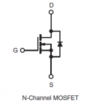
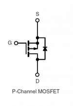
the bias on the lower mosfet is developed by the zener that sits on the negative rail. First off you have to be sure you have the mosfets mounted in the proper orientation, the source is going to be on the rail side, not to the output. Is it? Is it the proper type? Or are they reversed (likely). BOTH polarity, N or P channel, AND physical pinout have to be correct!!
The zener sets the bias directly so it has to be the proper voltage for the particular device you chose to use, it may be different than the 5.1v zener.
Since the upper mosfet's turn on voltage is set by the tubes via the adjustment in the tail of the LTP, the other half needs to be correct before it will balance for "0vdc" at the output.
You can test the lower mosfet alone, take the tube out, and disconnect the upper mosfet's resistor. Place a resistor to ground at the output... anything near 8 ohms will be ok. Now if the lower mosfet is biased up correctly (how many mA or A does it call for?) you should see the proper current through either resistor. D1 & R15 are a simple voltage divider.
Btw, this is essentially similar to the "It Thinks It's A Triode" SE Class A DC Coupled amp I put out in the mid 1990s... except I used a current mirror for the lower mosfet and a pair of Jfets for the input. The trick is to wrap a DC servo back to the adjustment transistor in the LTP tail! Of course you have to set up the amp for static dissipation before engaging the DC servo... I biased mine using 3 Hitachi Mosfets per rail in the output at 3.5 amps and only ~30vdc on the rails. This toasted out about 120watts of pure class A heat, and needed a heatsink with efficiency and FINS...
Along those lines I don't understand how this amp can be biased properly with 45 volts on the rails?? And I don't understand how it will maintain DC balance - it MUST have an output capacitor as shown.
_-_-bear
regardless it sounds like the mosfets are turned on almost fully if the rails are pulled way down.
so you need to measure the gate to source voltage, not to mention the current through the resistors.
the bias on the lower mosfet is developed by the zener that sits on the negative rail. First off you have to be sure you have the mosfets mounted in the proper orientation, the source is going to be on the rail side, not to the output. Is it? Is it the proper type? Or are they reversed (likely). BOTH polarity, N or P channel, AND physical pinout have to be correct!!
The zener sets the bias directly so it has to be the proper voltage for the particular device you chose to use, it may be different than the 5.1v zener.
Since the upper mosfet's turn on voltage is set by the tubes via the adjustment in the tail of the LTP, the other half needs to be correct before it will balance for "0vdc" at the output.
You can test the lower mosfet alone, take the tube out, and disconnect the upper mosfet's resistor. Place a resistor to ground at the output... anything near 8 ohms will be ok. Now if the lower mosfet is biased up correctly (how many mA or A does it call for?) you should see the proper current through either resistor. D1 & R15 are a simple voltage divider.
Btw, this is essentially similar to the "It Thinks It's A Triode" SE Class A DC Coupled amp I put out in the mid 1990s... except I used a current mirror for the lower mosfet and a pair of Jfets for the input. The trick is to wrap a DC servo back to the adjustment transistor in the LTP tail! Of course you have to set up the amp for static dissipation before engaging the DC servo... I biased mine using 3 Hitachi Mosfets per rail in the output at 3.5 amps and only ~30vdc on the rails. This toasted out about 120watts of pure class A heat, and needed a heatsink with efficiency and FINS...
Along those lines I don't understand how this amp can be biased properly with 45 volts on the rails?? And I don't understand how it will maintain DC balance - it MUST have an output capacitor as shown.
_-_-bear
Last edited:
I replaced Q1 just to be sure - no change.
Then I added a household bulb (DC resistance about 50 Ohms) in series with R2 (0.5 Ohms). The power supply voltage then settled at 36-0-36 ... which is fine! I measured the current through R2 at about 2 Amps ... also about right.
The original circuit called for IRF540 as Q1, with an Rds(on) of < 0.08 Ohms. The IRFP140 has the same Rds(on) and a higher current rating, so I don't see that the change of device is affecting the result
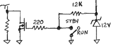
Look at this in standby the fet is off....
Can you turn Q1 off?....so the lamp goes out?
Regards
M. Gregg
Attachments
Last edited:
Just for interest.. By BEAR...
Check connections?
If it is the wrong way round you have a diode in conduction not a FET...
When testing don't just short out D1 or you will damage Q5.. so gate (disconnected from circuit) to lower rail via perhaps a 2K should turn it off..
I guess you have 10K resistance between PE and pin 7 tube..
Regards
M. Gregg
Attachments
Last edited:
On the OP's actual amplifier?
Who knows?
On the schematic?
You tell me.
Will 5.1vdc be the proper bias point for the mosfet the OP is using?
For sure something is wrong with the way the OP made the amp. The pinout on the actual Mosfet he used needs to certainly be checked. Your suggestion as to testing the lower mosfet's action is reasonable, but as I noted does not need to be made out of the circuit...
And the wrong way? Pulling a 45vdc down to 10 volts is a rather STRONG conduction, yes?
...let's see what the OP comes back with?
_-_-bear
- Status
- This old topic is closed. If you want to reopen this topic, contact a moderator using the "Report Post" button.
- Home
- Amplifiers
- Tubes / Valves
- Power supply issues with Borbely style 12AU7/MOSFET hybrid