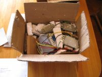
LOL, for a moment I thought the chassis was made from cardboard.
Doh!
https://picasaweb.google.com/aspringv/ChineseTubeAmpPics#5659930885357169874
Silly me
The 'scratch-prevention plastic covering was (one of the few) nice touches on mine as well.
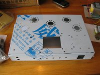
At least they have the cutout for the lay-down PT in your chassis. Perhaps they took my 'complaining' to heart. ??
Be sure to put grommets for the transformer through-chassis holes on your shopping list. You will likely have to enlarge the holes to suit.
Now- do the transformer covers actually cover the transformer mounting ears?
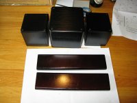
Oh, and grab a couple of pieces of hardwood (you have lots of good stuff in Oz..) for the end pieces and chuck that Chinese particleboard....
Pictures in the thread
Attempt #2 to get the pics in the thread.
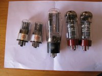
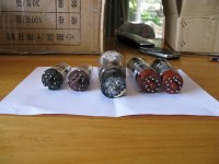
I've had word back from the vendor about the used bits, and he's certain that the valves are all NOS. He's also offered to refund some payment back for the missing parts, so all good there. The most amusing bit of the message was
"The 2pcs capacitors are used. That is because the caps are better than unused.
It is to make the sound better. Sorry for that."
...Anyway, I'm pleased for the offer to either replace or offer a wee discount, so we'll see how we get on.
With regards to hardwood, I absolutely agree - I'll be replacing the ends on it with something much nicer (and yup, there's quite a bit of jarrah in the shed ) I'll probably build it with the existing parts for now, with a view to replacing bits when I get a chance to. Fingers crossed I'll get a bit done this weekend!
Today was a rather long work day, so I'll give the build a shot tomorrow.
Attempt #2 to get the pics in the thread.
I've had word back from the vendor about the used bits, and he's certain that the valves are all NOS. He's also offered to refund some payment back for the missing parts, so all good there. The most amusing bit of the message was
"The 2pcs capacitors are used. That is because the caps are better than unused.
It is to make the sound better. Sorry for that."
...Anyway, I'm pleased for the offer to either replace or offer a wee discount, so we'll see how we get on.
With regards to hardwood, I absolutely agree - I'll be replacing the ends on it with something much nicer (and yup, there's quite a bit of jarrah in the shed
) I'll probably build it with the existing parts for now, with a view to replacing bits when I get a chance to. Fingers crossed I'll get a bit done this weekend!Today was a rather long work day, so I'll give the build a shot tomorrow.
Attachments
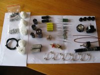
A wee little play with the parts
..reveals a few issues.
Firstly, there's no appropriate mounting holes to suit the output transformers, and as has been pointed out previously by Victoriaguy the flanges for mounting the output transfo's are not covered by the covers. Hmm.
That said the power transfo does actually fit the hole for it, so I'm at least somewhat slightly mollified.... and the cover fits appropriately
I reckon I'll buy a few tagstrips before I kick this off.
Yeah, a few issues, but as long as they are ones you can get around, it isn't too bad.
I'm looking forward to the end result dressed with some nice Jarrah
Edit:Just had a thought, can the output transformers be mounted with the flanges on the underside of the top plate and still be secure? Hmm...would mean a little metal work on the top plate or maybe a mod to the covers might be better? or making new covers might be easier damn, was hoping I could think of something to help
I'm looking forward to the end result dressed with some nice Jarrah
Edit:Just had a thought, can the output transformers be mounted with the flanges on the underside of the top plate and still be secure? Hmm...would mean a little metal work on the top plate
or maybe a mod to the covers might be better? or making new covers might be easier damn, was hoping I could think of something to help
Last edited:
Ok, started a bit of work on the unit today. I've ginned up a couple of hardwood sides for the unit out of jarrah offcuts from another project I've on the go (photo's when I'm done finishing them).
I'm using tagstrips instead of the buss style build also. I'm a relative point to point novice here so if anyone has layout suggestions I'd be glad to hear em.
Pics to follow shortly.
I'm using tagstrips instead of the buss style build also. I'm a relative point to point novice here so if anyone has layout suggestions I'd be glad to hear em.
Pics to follow shortly.
Nice thinking on the transformer mounting, straight forward with minimal energy spent
aspringv, with layout, try to keep it as symmetrical as possible, and as you would be doing anyway... keep signal and power apart. I have seen too many amps (especially retail) that have signal wires bunched with heater wires and such. Actually try to keep everything separate so you don't have fields from one wire influencing another, and where they have to cross, do so at right angles.
You are probably adhering to the above anyway, but thought I would just mention it.
Last edited:
going nicely
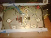
WIP photo. I've mostly wired up the power supply, although not as yet got the inductor in there. So far, kept it relatively tidy, but we'll see ho we go from here.
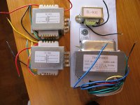
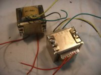
A few potential issues have come up. Firstly, I quickly fired up the transfo and got a few readings off it. All of the following readings are taken directly off the transfo without any load on it.
First up, the local mains is at 245V AC, whilst the transfo is wired for 220vac so all the secondaries are running a little high.
5v nominal- 5.8vac
6.3v nominal - 7.4vac
330v nominal - 365vac
So I'm a little concerned about these readings - I'll finish it all up and see what they read loaded.
Secondly, the schematic I'm following (attached, courtesy VictoriaGuy) states 1W resistors all round, and I'm wondering what the actual currents are at various points so I can see if I can substitute in some .25W parts I have on hand. Failing that I can just parallel up 4 at a time, but I'd rather avoid that if possible. The only exception to that is the 250R 5W off pin 8 of the EL34 - and I was wondering what the ramifications of using the supplied 330R parts would be? If someone with an understanding of how the circuit actually works could let me know that'd be helpful
Cheers all!
WIP photo. I've mostly wired up the power supply, although not as yet got the inductor in there. So far, kept it relatively tidy, but we'll see ho we go from here.
A few potential issues have come up. Firstly, I quickly fired up the transfo and got a few readings off it. All of the following readings are taken directly off the transfo without any load on it.
First up, the local mains is at 245V AC, whilst the transfo is wired for 220vac so all the secondaries are running a little high.
5v nominal- 5.8vac
6.3v nominal - 7.4vac
330v nominal - 365vac
So I'm a little concerned about these readings - I'll finish it all up and see what they read loaded.
Secondly, the schematic I'm following (attached, courtesy VictoriaGuy) states 1W resistors all round, and I'm wondering what the actual currents are at various points so I can see if I can substitute in some .25W parts I have on hand. Failing that I can just parallel up 4 at a time, but I'd rather avoid that if possible. The only exception to that is the 250R 5W off pin 8 of the EL34 - and I was wondering what the ramifications of using the supplied 330R parts would be? If someone with an understanding of how the circuit actually works could let me know that'd be helpful
Cheers all!
Attachments
245vac - Yeilding some,er, exciting, voltage numbers
So I powered up the default psu circuit and got...
B1 - ~490V
B2 - ~478V
B3 - ~134V
Given to date I've only ever built transistor amps, I'm still moving my brain up an order of magnitude in terms of expected voltages...
OK, so this has arisen due to the secondaries being 330V (not the 290V on the original schematic), and the mains being 245VAC instead of Australia's nominal 230VAC...
So, can I throw this one out to the collective Diyaudio brains trust? The target voltages in the Ezekiel circuit are B1 278V, B2 260V, so I'm a hell of a long way over these... What to do?
Last edited:
First up, the local mains is at 245V AC, whilst the transfo is wired for 220vac so all the secondaries are running a little high.
5v nominal- 5.8vac
6.3v nominal - 7.4vac
330v nominal - 365vac
So I'm a little concerned about these readings - I'll finish it all up and see what they read loaded.
This might help with your mains problem:
http://www.apcmedia.com/salestools/MMIS-8F9K8V_R0_EN.pdf
APC Line-R 600VA Automatic Voltage Regulator, Schuko Outlets, 230V
how far to go
Is anyone able to suggest maximum reasonable values for B1, B2 and B3?
And can anyone speculate the current draw on the supply from each of these points?
I've been playing about with simulations of the psu circuit and in order to see what I'm up against in terms of RC filters and subsequent total current draw. To really get a feel for whats going on these values would be helpful if anyone could assist?
I might just summarise my various plea's for help shortly
Places of 1/4 Watt resistors: 100K in the 1st triode, 270K in EL34 grid, 4K7 in feedback network.
Other : Better with 330R in EL34 cathode, esp. considering your high line voltage. No time to do any calculations yet.
Also: I do not see ant gridstopper resistors.
I cant remember if it has been mentioned, but better way is to have one 6SN7 as the "upper" valve in both channels ans the other 6SN7 as the "lower" one. That way you stress less the cathode-heater insulation.
That's it for now, maybe I ll think of more later.
As Costis has mentioned, the EL34 cathode resistor 'controls' the current flowing through the power tube, so if you increase the B+ voltage you will need to increase the resistor value to keep the currrent the same. (Ohms law). It's pretty common to have to tweak/adjust the cathode resistor value to keep the plate dissipation (in watts ie volts x amps) within limits.
I wouldn't get too excited about the higher voltages until you power up the amp with tubes (and dummy load or speakers). The power transformer supplied with my 'kit' is 'just big enough' to do the job, and I'd expect to see a voltage drop once it is put to work.
As rock4016 suggests, dropping the B+ is fairly simple. If your heater voltages are much over spec, that would be a bigger problem, I think, as it can reduce tube lifetime.
- Status
- This old topic is closed. If you want to reopen this topic, contact a moderator using the "Report Post" button.
- Home
- Amplifiers
- Tubes / Valves
- Cheap ($235) SE Tube amp kit, transformer and chassis on ebay