costis_n - what do you propose? The point for me here is a learning exercise, so I'm happy to explore the options available. And cheers for the resistors answer and the note on separating the 'top' and 'bottom' tubes.
With regards to the heater voltages being over spec, I'm considering rectifying em and regulating them; but I'll save that for later in the piece I think. I'll get it all up and running first...
With regards to the heater voltages being over spec, I'm considering rectifying em and regulating them; but I'll save that for later in the piece I think. I'll get it all up and running first...
This is the circuit I propose.Most parts are same, operating points too. Excuse the crappy Photoshop ok? ") Similar to what I have built.
Similar to what I have built.
Similar to what I have built.An externally hosted image should be here but it was not working when we last tested it.
and the advantages of this layout are?
If you don't mind taking the time to explain, what do you see as the advantages of this layout?
I can see that you've eliminated the GFB loop, and you no longer have an SRPP front end but if you could point me to some discussion of the circuit or similar so I can develop a bit more understanding about how it works that'd be appreciated.
Cheers for the input though - whichever way I decide to go with the build, this represents another alternative to the standard layout of the 'kit' parts.
It is just a grounded cathode stage followed by a cathode follower (so there is still feedback, but local) and these two together have a constant current draw. more info here CCDA: constant-current-draw amplifier
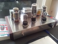
...And finally finished.
It's taken a little while, but I appear to be finally (almost!) finished with this project.
I went with the Ezekiel circuit in the end; many thanks for the link to that schematic and the help on the way. My concerns around the voltages of the PSU seem to be unfounded - she's settled down to a B1 of 370v or so (schematic was 278) and a B2 of 316V (schematic 260V), so I'm in two minds as to whether or not to do anything about it. She does sound pretty good, but part of me want's to keep tinkering to see if it'll sound better closer to the target B+ voltages...
No hum or hiss at all, and it sounds pretty good right now (Billy Bragg - Back to Basics), but was a little muddled listening to denser materiel (Hip Hop/Electronica) through transmission line speakers with 89dBm sensitivity (volume at about 40%).
The power transfo runs quite hot - ambient temp at the moment is about 24C, and the transfo is at 50C, which is too hot to hold my hand on for more that a couple of seconds. I'm considering heatsinking it, but she looks a bit too pretty to do that to! I'll leave the cover off and see how it goes.
I did replace the side covers with some jarrah (burninshed with tung oil) but annoyingly the sides didn't quite line up right so when it irritates me enough I'll pull it apart and make the mounting holes a bit bigger and try again
Cheers all for the help - I'm off to do a bit more critical listening
Attachments
You mentioned that you have 370V for B1. What voltages do you get on the EL34?
Pins 1 and 8 should be strapped together - what voltage there? About 22V or so?
Pins 2 and 7 should be no higher than 6.5VAC (6.3VAC is the desired voltage). If this is very much higher you will be burning up the tubes too quickly.
Pin 3 - 360V
Pin 4 - 315V
Pin 5 is the control grid (input)
Pin 6 - unused
--
It looks very niceIt's taken a little while, but I appear to be finally (almost!) finished with this project.
snip!
Cheers all for the help - I'm off to do a bit more critical listening
A highly delayed addendum
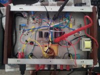
I finally got around to completing the amp properly. After much tinkering with the power supply circuit I achieved suitable voltages for the tubes... Having moved to a house with a mains voltage of around ~230VAC helped somewhat also! The power transformer now sits at a much more comfortable temperature, and I'm happy to put the covers on now.
For potential Australian builders the power supply is detailed on the attached diagram - the power dissipation on the 470R is high (~10W or so) so I bought a 25W ally housed power resistor, heatsinked to the chassis to deal with it. The chassis sits at a temp of 63C on the spot directly opposite where I mounted the resistor... so perhaps a notice of do not touch is in order. :/
Final performance is pretty good. I'm running on a set of (4 ohm) test speakers for a while, and listening reveals an over pronounced mid range. My only difference over the Ezekiel circuit is 330R on the el34 tubes; and perhaps, now I have optimal voltages on the tubes, a change to the specified values is in order before pronouncing a final judgement on the project.
The power switch has proved to be an ...erratic performer so it needs changed, but otherwise I got what I paid for and I'm happy with the results. I certainly didn't go for boutique components through the build, in keeping with the budget origins of the unit.
I'll update again after the resistor change.
Attachments
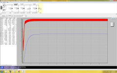
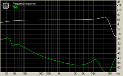
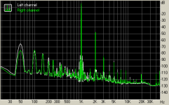
Thought this data would be of interest
I've (only just) started having a play with RMAA and thought I'd throw this amp on for testing. The load was a 4.7R wirewould and ally housed and the terminal on the amp used was the 4 ohm one.
Results below.
I've (only just) started having a play with RMAA and thought I'd throw this amp on for testing. The load was a 4.7R wirewould and ally housed and the terminal on the amp used was the 4 ohm one.
Results below.
Attachments
and very belated news...
I changed the gnf caps to some mica units and the sound has come alive. I was nonplussed earlier in the process, but she sounds pretty good now.
Critical listening reveals a somewhat tubby bottom end, but a pleasant mid predominates, so in the end I call her a win. Reccomended!
I changed the gnf caps to some mica units and the sound has come alive. I was nonplussed earlier in the process, but she sounds pretty good now.
Critical listening reveals a somewhat tubby bottom end, but a pleasant mid predominates, so in the end I call her a win. Reccomended!
- Status
- This old topic is closed. If you want to reopen this topic, contact a moderator using the "Report Post" button.
- Home
- Amplifiers
- Tubes / Valves
- Cheap ($235) SE Tube amp kit, transformer and chassis on ebay