Again. Have done some testing as I posted in the 26 pre-amp thread.
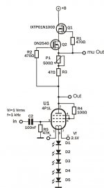
Attached is my modular test bed using Gluca's board for the IXYS Mosfet CCS. Filament and HT supply is regulated from my lab power supply.
So, after a testing several operating points I came up with the best one in terms of distortion:
Ia=25mA, Va=77V, Vg=-5.8V (LED array combination of amber and red ones)
THD = 0.019%. Slightly better compared to my best 26 valve measure. I just tested one 4P1L which I had at hand, may need to check if there is a more linear one, however, as it stands the result is really good compared to other valves!
Any suggestions around trying a different op point? What about biasing around -15/-20V and increasing the anode voltage? Will improve distortion?
Thanks
Ale
Attachments
Ive played around with the 4P1L....
Wow! Incredible Microphonics! That things ring like a bell if you make any harsh vibration, and if you tap 'em they ring for many seconds!
I was running about 80V anode and around 25mA with a MOSFET on top, and std cathode bias un-bypassed.....
Wow! Incredible Microphonics! That things ring like a bell if you make any harsh vibration, and if you tap 'em they ring for many seconds!
I was running about 80V anode and around 25mA with a MOSFET on top, and std cathode bias un-bypassed.....
Ive played around with the 4P1L....
Wow! Incredible Microphonics! That things ring like a bell if you make any harsh vibration, and if you tap 'em they ring for many seconds!
I was running about 80V anode and around 25mA with a MOSFET on top, and std cathode bias un-bypassed.....
Hi Alistair,
:-( that doesn't sound very encouraging though. I did tap it whilst driving it with a 1kHz sine signal and couldn't see any traces of ringing in the scope...
Well, I got very close with the operating point anyway!
Will have to build and test this on a real amp...
Thanks
Ale
Maybe its the tubes I was using, I have 4 'svetlana' ones and 4 of some other make, They all rang like bells!--Although slightly different tunes!...
I had arranged the test as the first stage in an amp just to see what they would be like.
I was using a SLA batt to supply the heaters via current limiting resistor, and had it triode-strapped....
I had arranged the test as the first stage in an amp just to see what they would be like.
I was using a SLA batt to supply the heaters via current limiting resistor, and had it triode-strapped....
I had arranged the test as the first stage in an amp just to see what they would be like.
I am afraid it is overkill to use power output tube for the first stage in an amp, unless it is also the last one.
")
So--Probably overkill to use one in a Line-Stage too you reckon...?
I did not try that, but in output stage they did not ring.
I think that in a power-amp, the step-down ratio of the output transformer probably lowers the level of the ringing considerably. (At leaast I hope so! as I intend to build one soon) As a preamp, they ring if any loud noise is made in the room, although admittedly, I have done nothing in the form of damping for them, as this pre is still an experiment.
The idea of putting leds in the cathode is to give it constant voltage. But leds have rather high dynamic impedance. I did some measurements to determine the Rdc of leds by changing the current through them and measure the voltage difference and found the following values: Red 5 Ohm, Green 15 Ohm, Yellow 18 Ohm and Blue 37 Ohm. When you put a string in the cathode these Rdc values add.
Mogliaa:
In my ears bias with leds alone sound only so so.
Try to bypass the leds in your schematic in post #21 with good quality foil types and listen to the differences with/without. I am sure it will put a smile on your face!
My recipe is to start with something big and bypass it with several capacitors from large to very small, for example: 10u mkt or pp, bypassed with 2.2u pp, then 100n polystyrene, 10n polystyrene, 3n Russian Teflon, 560p Russian Teflon. Or whatever types you prefer or have on hand! Even the smallest values in the pF region give an easy to hear improvement, so don't forget these.
Peter
Last edited:
My LED's are bypassed with new OSCON organic caps. I tried quite a few different types here and these give best balance and clarity in my system with my current operating point. They are ULTRA-low ESR. No small bypass caps needed.
I know, but have you tried it? I mean small high quality bypass caps.
I xan't remember exactly what I did at the time, but I do know I tried quite a variety of different cap combinations. The OSCON's were the first caps to bring out the midrange the way i wanted. All other combinations were too thin-sounding. Maybe I will try again one of these days. I haven't spent too much attention on it as I don't intend it to be my permanent pre. Tired of the ringing!
The idea of putting leds in the cathode is to give it constant voltage. But leds have rather high dynamic impedance. I did some measurements to determine the Rdc of leds by changing the current through them and measure the voltage difference and found the following values: Red 5 Ohm, Green 15 Ohm, Yellow 18 Ohm and Blue 37 Ohm. When you put a string in the cathode these Rdc values add.
Mogliaa:
In my ears bias with leds alone sound only so so.
Try to bypass the leds in your schematic in post #21 with good quality foil types and listen to the differences with/without. I am sure it will put a smile on your face!
My recipe is to start with something big and bypass it with several capacitors from large to very small, for example: 10u mkt or pp, bypassed with 2.2u pp, then 100n polystyrene, 10n polystyrene, 3n Russian Teflon, 560p Russian Teflon. Or whatever types you prefer or have on hand! Even the smallest values in the pF region give an easy to hear improvement, so don't forget these.
Peter
Hi Peter,
Will try bypassing the leds. Have some PIO around and will give them a try...
thanks
Ale
Unbypassed leds will sound a lot bettter bypased. Even when you use 4.7uF MKT. Let us hear what you think of it!
Peter
Hi Peter,
Your experience with LEDs somewhat contradicts my own, although I have run into some red leds with a dynamic impedance that was much higher than I expected. Just wondering how you measure the dynamic impedance of LEDs - might be something I could replicate here. I have not measured anything but bad red leds, (>10 ohms) and IR leds which had very low impedances of only an ohm or so..
I also haven't found bypassing them with capacitors in most cases to be of significant benefit, so I am wondering what in our experiences makes our two conclusions so different.
Just curiosity on my part, seeking to understand something I may not understand as well as I thought..
Thanks, Kevin
The way I measured the dynamic impedance is not really scientific, but what I did is change the DC current trough the leds (bench power supply and 1k resistor in series with the led) and measure the change in DC voltage across them. Rdyn.= ΔU/ΔI.
First I have tried bypassing them with Elna Silmic but with no positive results and later with foil capacitors with good results.
First I have tried bypassing them with Elna Silmic but with no positive results and later with foil capacitors with good results.
Kevin, IMLE the bypass caps have to be very low ESR or uinexpectedly large value to make an appreciable difference - probably because the resistance they are bypassing is not a very large value. It may seem counterintuitive, but in my experiments, larger values than you might expect are required. As mentioned earlier, I found the Oscon SEP organic caps to be very effective for this job (at least in this particular preamp at its particular OP). I have 330uF 16v SEP's in there. Perhaps the difference won't be so audible in a "run of the mill" IDHT, though I did find it audible with 6CG7's in a previous incarnation of this pre.
OK, I have been needled into experimenting with "bypassing the bypass". I just spent a few enjoyable hours trying out various bypass caps (with clip-leads). I used fairly complex music with a lot of high frequency information - Mike Oldfield - Voyager. I chose tracks with busy passages and bagpipes and all sorts in the mix and turned up the volume enough so that it began to sound a little harsh and slightly muddled - then I looked for caps that could smooth that slight harshness and resolve the slight muddle. You might try a different approach, but this was the only way I could hear any differences that would be useful to me at this point.
Results? - Differences are not "night and day". Subtle, but slightly audible with some effort and a couple of different tracks. Clip-leads allowed me to quickly change caps back and forth until I found a difference or decided there wasn't a significant one. Once I had selected the ones I was most interested in, I spent time listening, both nearfield and further away. That stage is still in progress. I will probably spend a couple of days with each choice before making a final decision.
Small values were disappointing. They made no audible difference in almost all cases - probably because of the already extremely low ESR of the Oscons (16 milliohms according to their spec-sheet). I would expect different results bypassing other types of capacitors.
I tried K75 0.22uF; Wima 0.47 and 1uF; Mundorf Mcap Supreme Silver/oil 0.33uF and silver/gold 0.1uF; ICW 0.47 and 1uF; Ft1 1200p; FT3 0.1uF; Jimson - 0.22 and 0.47; vintage PIO 3.75uF and the famous ERO Kp1837 22nF.
I currently have the 3.75 PIO's hooked up. They sound best at first listen, but slow the music down a tad and roll off the HF slightly. Don't know if I can live with them long-term - and physical size is a real issue. They are 120mm x 35mm each, whereas the board with led's and resistors measures 50mm x 30mm. Next best were the Mundorf silver/gold 0,1uF and the ICW 0.47uF. Each had their strong points. Both offered a noticeable improvement in clarity. The ICW offered a slightly better balanced, fuller sound, whereas the Mundorf offered a little bit more emotional involvement. ICW 1uF was no better than 0,47uF. I found that the Mundorf Silver/oil, in spite of its larger value, was as big a disappointment in this application as it was in all the other applications I have tried it in. I expected a lot from the FT3, but there was no audible difference with it, nor with the other Teflon's except the K75 (where difference was barely discernible at best). I am convinced that larger value Teflons would have been better - maybe even the best - but I had none to hand, and of course their size is another big problem (excuse the pun!).
I will probably hook up the ICW 0.47s in the end. They are a sensible size, offer a good balanced sound with a definite improvement in the smoothness of the treble, and don't cost an arm and a leg. The PIO's have the smoothest sound by far, but too many other drawbacks. As for the Mundorf's, it really rubs me up the wrong way to use the Supreme series caps, rated for 1200v DC and costing plenty, to bypass a bypass cap in an 8,5v LED string! I keep hoping I will find a more worthy use for them - maybe in a power amp.
Of course, it goes without saying that these results are for my system, with my current front-end, power amps and speakers. A change in any of these would probably necessitate a whole new round of experiments to find the best balanced sound. Are we DIY'ers crazy or what?! (Well I guess I must be anyway)
Hope someone finds this to be of interest.
Regards,
William.
The way I measured the dynamic impedance is not really scientific, but what I did is change the DC current trough the leds (bench power supply and 1k resistor in series with the led) and measure the change in DC voltage across them. Rdyn.= ΔU/ΔI.
First I have tried bypassing them with Elna Silmic but with no positive results and later with foil capacitors with good results.
Pretty much what I do, but I am wondering as the results I get are always significantly higher than the data sheet values.. I'm thinking about making a jig where I modulate the DC constant current with a defined AC current and then measure the AC voltage component developed across the LED..
Hey, is this science? No. But it is fun!
Thanks for the description, most useful and quite interesting.
I have not tried large value oscons across LEDs because I have found them a little difficult to get, and could not hear significant differences with any of the other caps I tried - even quite large values. What I can say is that very large electrolytics like the Muse sound terrible with very low DC voltages across them and even smaller signal voltages in conventional cathode bias configurations. Even the Blackgates need substantial bypassing with smaller caps of various sorts. I don't understand the distortion mechanism, but you can't see it on the bench with static sine waves, but you can sure hear it on music. My recollection is you could see it with sine bursts. In those sorts of applications I now use fixed bias or IR leds which really do seem to have very low dynamic resistances for the most part.
- Home
- Amplifiers
- Tubes / Valves
- 4P1L DHT Line Stage