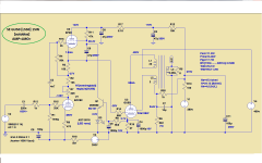
While on vacation last week I was reading several articles on Mu stages/followers and came to the conclusion that a Mu stage with a Pentode on top might make a good driver for a sweep tube as a SE output.
I had recently read Karpov's article "SPECTRA" on the output spectrum of several Soviet Union tubes and decided to try the 6P41S. It looks like it should be nice in Triode mode, and might be worth listening to in Pentode mode with a little plate to previous grid feedback.
I decided to try direct coupling the output of the Mu stage, which requires level shifting, or a minus supply for the lower triode. Using a little sand for feedback to control the minus supply and thus the drive to the output tube grid looks promising in simulations.
An alternative method would be to put a series resistor in the B- supply and use current sink control to adjust the B_ to the lower tube.
The circuit needs some tweaking as the Mu stage currently is only running 1mA of current and more will be required if A2 is to be achieved.
Comments and recommendations welcome.
Attachments

Last edited:
Hi Steven,
Yes, Pentodes make good CCS and thus perform well as upper tube in µ-followers.
Indeed a nice circuit but there are some issues to discuss.
1mA is a bit low. Yes it's a pentode power stage and miller capacity shouldn't be a problem, but I've listened to many amps and I alway prefered a stronger driver. By the way, the 6Н1П likes higher currents and you can clearly hear that.
Of course, low currents are nice in µ-stages cause that means high upper-tube-cathode-resistors @ fewer voltage drop and that leads to better constant current sources. But the more this stage has to drive, the more its concept fails.
So I suggest you not to use the EF86 as upper stage. You could use it triode connected as lower stage. But for the upper stage I would take a typical wide-band Pentode with 5mA to 10mA current and higher gm.
Next thing is your feedback. You're using parallel derived and parallel applied feedback, effectively from the Anode of the power tube back to its grid. But the problem is, you are applying it on the Anode of the driver tube, that tube of which the current should be constant ! See the Problem ? That resistor (R7) destroys your CCS (a little bit, since it's rather large, but remember that the power tube can swing to twice the Ub)
Also bear in mind that this kind of feedback reduces not only the output resistance but also input resistance.
Another Feedback option is the cathode of the first tube. So you have the good old parallel derived, series applied feedback. (reducing output and increasing input resistance)
Finally I hope you know that you're dealing with sweep tubes. I tested them often times and in SE single ended the didn't sound impressive.....
regards
The mu-follower gives low output impedance but not particularly good drive capability - especially with an EF86 running at a mA! You have destroyed the whole point of the circuit (high impedance load for the lower anode, so low distortion) by sending feedback to the lower anode. If you mix bits from different good circuits together you need to be aware that the whole can be significantly less than the sum of its parts.
You would need a complete redesign to drive the output into A2.
You would need a complete redesign to drive the output into A2.
The ss circuit takes care of keeping output tube grid1 bias negative. I don't know if this is called a servo or not. It simply adjusts the lower triode cathode supply to move the plate of the triode and thus the drive to the next grid.
Since the upper tube is configured as a current source this can be done with a simple regulator using the grid voltage as feedback.
This may require a delay in the B+/B- supplies to insure proper bias of the output tube during power up.
Using a Mu stage to drive a dc coupled SE output is what I was interested in experimenting with.
A2 operation was more of an afterthought once I got the basic circuit designed, it is not required but I am interesting to play with. What I have not been able to find out is how much current is needed for positive g1 drive.
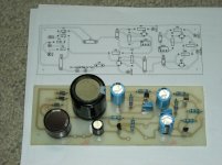
The breadboard worked fine, so I made a PCB for further testing. First PCB in 30 years and it worked on the first pass, although there are pinholes in the traces due to the poor mask quality I got printing on overhead viewer film with a HP Deskjet printer.
I used some 10 year old GC positive sensitized board with red devil lye for developer and Easy Off oven spray to remove the remaining mask after etching.
DipTrace was the easiest layout program I tried so I'm going with it.
Quick and easy.
I used some 10 year old GC positive sensitized board with red devil lye for developer and Easy Off oven spray to remove the remaining mask after etching.
DipTrace was the easiest layout program I tried so I'm going with it.
Quick and easy.
Attachments
I finally got around to bread-boarding the entire amp.
I set the bias with the 6P41S out of the socket. It was necessary to change a couple of resistors to get the bias where I wanted it. Once bias was set to -30V I powered it down and installed the 6P41s, and powered it up. Vg 6P41S surges to 106 for several seconds, but no current spike was seen. Vg 6P41s rapidly drops to proper bias around -30V, so I suspect the thermal delay of the driver cathodes is much lower than the thermal delay of the 6P41S allowing bias to be achieved before conduction takes place in the 6P41S. A delay circuit of some sort may be a good idea and will be investigated later.
The 6P41s went Red-Plate after warming up. With B+ at 270V in UL, Vg2 was way out of spec. I changed the screen resistor from 470R to 15K with a 1uF bypass cap and idle current dropped from 250mA to 125mA. Adjusting Vg1 brought it down to 95mA.
Looks like I need to go back to the thread about reducing the screen voltage for UL operation with various techniques to optimize the design as the 15K resistor bypassed with 1uF rolls off my LF response.
As a note, the 6P41S takes a lot of drive voltage and a lot of bias (-30V) compared to a 6L6 at -20V!
After getting the amp running I played around with UL and Triode modes, but didn’t try Pentode mode yet.
The granddaughter and I listened to Lee Roy Parnell “Back to the Well” and Bonnie Raitt “Green Light”, and decided we like UL better although Triode sounded nice and may be better suited for some music. It sounded to me like it was going burst oscillation on peaks so I need to investigate that.
The 6P41S will take almost 125mA at 240V before going red plate. That is 30W and way beyond the 12W data sheet rating!!!. I may have to try a PP amp with them once I finish this SE amp. I suspect a 50W AB1 PP amp is possible with a pair of these tubes, although forced air cooling may be required. AB2 looks interesting as well. The tubes are HOT at 30W!
I bumped something with my elbow and the amp shut down, so I now have some debugging to do.
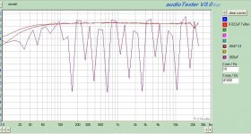
When I ran some frequency response plots last night I got a strange result when I tried a .068uF KY42y-2, per the attached plot.
The plot jumps up and down over 20dB with jaged edges.
I tried a second KY42y-2 with the same results. When I put the KY40y-9 back in it plotted with a smooth curve.
I cant' upload the plot right now for some reason. My browser crashes wehn I try. I'll try again later from home.
The plot jumps up and down over 20dB with jaged edges.
I tried a second KY42y-2 with the same results. When I put the KY40y-9 back in it plotted with a smooth curve.
I cant' upload the plot right now for some reason. My browser crashes wehn I try. I'll try again later from home.
Last edited:
Thanks guys,
I've got a question about the power supply.
My plan is to run the Antek AN-1T200 transformer with both secondaries full wave bridge rectified. I plan on tying the two secondary outputs together at the input of the filter choke (no room for two chokes or I'd run separate supplies for both channels).
I think I need equalizing resistors in series with the two B+ lines where they tie together. I was planning on placing the two resistors in line with the bridge outputs to a single filter cap, then go to the Inductor, second filter cap , then 100R resistors splitting the supply to the individual channel filter caps.
Is there a better way given the constraints of single inductor and 5 filter caps (not including the 40uF film caps)?
Attachments
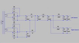
I decided the transformer resistance would be sufficient and just tied the two bridges together. This feeds a 300uF cap bank, then a 8H inductor, 330uF, followed by twin 100R resistors to the final 220uF caps for the plates. There are two 40uF film caps in parallel with the 220uF electrolytics. There is a 1K5 resistor from here to an additional 47uF electrolytic and 1uF film cap for each preamp stage.
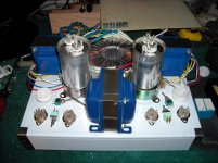
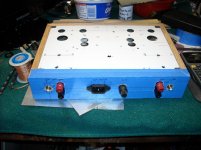
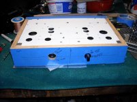
Completed drilling and milling tonight (I hope).
Completed drilling and milling tonight (I hope).
Attachments
model 6P41S
Hello!
This model can help, I like your amplifier and tube 6P41S think is very good audio projects
*LMO_model Koren style
*klausmobile datasheet
.SUBCKT 6P41S 1 4 2 3 ; P G2 G1 K (PENTODE)
.PARAMS: MU=18.368 EX=0.602 KG1=230.00 KP=160.8 KG2=600 KVB=25.8 CCG=3.0P CPG1=2.9P CCP=1.9P RGI=2K;
RE1 7 0 1G ; DUMMY SO NODE 7 HAS 2 CONNECTIONS
E1 7 0 VALUE={V(4,3)/KP*LOG(1+EXP((1/MU+V(2,3)/V(4,3))*KP))} ; E1 BREAKS UP LONG EQUATION FOR G1.
G1 1 3 VALUE={(PWR(V(7),EX)+PWRS(V(7),EX))/KG1*ATAN(V(1,3)/KVB)}
G2 4 3 VALUE={(EXP(EX*(LOG((V(4,3)/MU)+V(2,3)))))/KG2}
RCP 1 3 1G ; FOR CONVERGENCE
C1 2 3 {CCG} ; CATHODE-GRID 1
C2 1 2 {CPG1} ; GRID 1-PLATE
C3 1 3 {CCP} ; CATHODE-PLATE
R1 2 5 {RGI} ; FOR GRID CURRENT
D3 5 3 DX ; FOR GRID CURRENT
.MODEL DX D(IS=1N RS=1 CJO=10PF TT=1N)
.ENDS
While on vacation last week I was reading several articles on Mu stages/followers and came to the conclusion that a Mu stage with a Pentode on top might make a good driver for a sweep tube as a SE output.
I had recently read Karpov's article "SPECTRA" on the output spectrum of several Soviet Union tubes and decided to try the 6P41S. It looks like it should be nice in Triode mode, and might be worth listening to in Pentode mode with a little plate to previous grid feedback.
I decided to try direct coupling the output of the Mu stage, which requires level shifting, or a minus supply for the lower triode. Using a little sand for feedback to control the minus supply and thus the drive to the output tube grid looks promising in simulations.
An alternative method would be to put a series resistor in the B- supply and use current sink control to adjust the B_ to the lower tube.
The circuit needs some tweaking as the Mu stage currently is only running 1mA of current and more will be required if A2 is to be achieved.
Comments and recommendations welcome.
Hello!
This model can help, I like your amplifier and tube 6P41S think is very good audio projects
*LMO_model Koren style
*klausmobile datasheet
.SUBCKT 6P41S 1 4 2 3 ; P G2 G1 K (PENTODE)
.PARAMS: MU=18.368 EX=0.602 KG1=230.00 KP=160.8 KG2=600 KVB=25.8 CCG=3.0P CPG1=2.9P CCP=1.9P RGI=2K;
RE1 7 0 1G ; DUMMY SO NODE 7 HAS 2 CONNECTIONS
E1 7 0 VALUE={V(4,3)/KP*LOG(1+EXP((1/MU+V(2,3)/V(4,3))*KP))} ; E1 BREAKS UP LONG EQUATION FOR G1.
G1 1 3 VALUE={(PWR(V(7),EX)+PWRS(V(7),EX))/KG1*ATAN(V(1,3)/KVB)}
G2 4 3 VALUE={(EXP(EX*(LOG((V(4,3)/MU)+V(2,3)))))/KG2}
RCP 1 3 1G ; FOR CONVERGENCE
C1 2 3 {CCG} ; CATHODE-GRID 1
C2 1 2 {CPG1} ; GRID 1-PLATE
C3 1 3 {CCP} ; CATHODE-PLATE
R1 2 5 {RGI} ; FOR GRID CURRENT
D3 5 3 DX ; FOR GRID CURRENT
.MODEL DX D(IS=1N RS=1 CJO=10PF TT=1N)
.ENDS
LAZAROIU, thanks. I'll try your model tonight.
My apology for not addressing some of the issues raised by the_manta and DF96.
I became distracted by a stability issue with the servo and created another thread to address it. This resulted in several variants of the servo loop, including one with a triode as the control amp driving the screen of the upper 6J9P (best from a stability standpoint) and finally I gave it up on the servo and went to fixed bias with capacitive coupling for simplicity.
http://www.diyaudio.com/forums/tubes-valves/200384-closed-loop-stability-help-needed.html
On the bias current, I agree that 1mA is too low. I finally got a model for the 6J9P and have it running 5ma instead. (There was a note on the original schematic the target was the 6J9P).
For a number of reasons, I have not supported A2 operation.
With regards to the Schade feedback (R7), that has been removed.
With respect to Sweep Tubes not sounding good in SE mode, this is generally true. However, I understand that this tube is one of the exceptions. So far, listening tests bear this out.
I will post a schematic tonight.
Last edited:
recomandare
Good morning!
I can not help than what I've done, but with GU50 tube, of course if you do PSF for 6P41S can successfully use it.
If it is useful, it is schematics used by me and works very well, is very stable.
I think MU-FALOWER tubes [ECC82, EF80] you can find it easily because they are classic tubes, but I think they also have Russian equivalents.
The schematic are posted all values of voltage and currents in the essential point.
I hope something will be helpful.
A good day!
Attachments
- Status
- This old topic is closed. If you want to reopen this topic, contact a moderator using the "Report Post" button.
- Home
- Amplifiers
- Tubes / Valves
- Another SE amp design.