I’m working on a two stage amp using ECC99s and Sovtek 6B4Gs and trying to fit it to existing power and output transformers. I’m working with published curves and trying to balance supply voltage and operating points.
As it is set right now both stages will run into positive grid voltage before they cut off. Assuming that the curves I am using are accurate it would take 2.75Vrms input to swing the output grids to 0 volts and 4.25Vrms to swing first stage to 0. That gets me enough of a required supply voltage difference between the stages to allow for about 220 Ohms R in a PS filter to isolate the stages.
I don’t have the experience to make judgment call and this is way past my “oh no problem” point. I can’t figure out what would happen if either of the stages needed power on the grid but to be conservative I am assuming that the driver and preamp cannot supply any real current. (I have verified that the driver idle current will handle the input capacitance of the output)
So, since I am working from published curves, am I running things too close to the edge or is this close enough to try building?
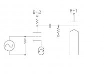
 Please post a schematic of your proposed topology and some hard numbers regarding your operating points, and we'll go from there.
 Sorry I wasn’t clear. 2.75 Vrms at the input gets full class A output from the 2nd stage 4.25 Vrms at the input will swing the input grid to 0 volts which I am taking as the limit. Is the 1.5 volt difference between getting full output and swinging the first stage grid positive enough headroom?
Attachments
Sorry I wasn’t clear. 2.75 Vrms at the input gets full class A output from the 2nd stage 4.25 Vrms at the input will swing the input grid to 0 volts which I am taking as the limit. Is the 1.5 volt difference between getting full output and swinging the first stage grid positive enough headroom?
I'm still a bit confused. Here's how I read your statement:
At 2.75 Vrms in, the output stage delivers full output power (which I take to mean the onset of clipping).
At 4.25 Vrms in, the input stage is at the limit of positive grid current (but the output stage is deep into clipping by then).
So your output stage clips way before your input stage. That sounds pretty solid to me. 1.5 Vrms is huge headroom. I don't see any serious degradation in measured THD until the peak input voltage is within 250 mV of the cathode voltage. But that depends on the tubes used and such. But 1.5 Vrms - don't worry about it.
I take the current source you've drawn in the cathode of the input tube should be a voltage source. Otherwise the circuit won't work...
~Tom
Hi Tom,
Yes you have it right, thanks for the reply
Marty
- Status
- This old topic is closed. If you want to reopen this topic, contact a moderator using the "Report Post" button.