I have yet to actually apply the NFB, but I am ready to do now. I just wanna be sure if the NFB signal should be in-phase or inverted from the input signal ?
It should be in-phase. The signal input is the non-inverting input, and the gNFB is connected to the inverting input. Just like an op-amp. Unlike op-amps, or OTLs, polarity isn't so apparent due to the OPT.
Connect a 8R, high wattage power resistor to the output, o-scope the output, and see what happens. If Mr. Murphy wired the OPT for positive feedback, you will see a large, somewhat square wave, across the output load resistor at ~25Hz (more or less depending on the OPT) as the whole amp makes like a Royer oscillator. (Which is why you want to use a resistor and not the speeks as the test load.)
If that happens, then reverse the plate and screen connections at the OPT primary to reverse the polarity.
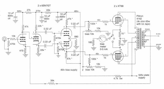
Thank you all for the response ... I kinda figured it had to be in-phase. Strange enough is that the schematic on the Plitron is wrong. I will have to swap the phase somewhere. BTW the long drawn out story of trouble shooting this amp is on this thread
http://www.diyaudio.com/forums/tubes-valves/182955-problem-my-amp-i-have-run-out-ideas.html
http://www.diyaudio.com/forums/tubes-valves/182955-problem-my-amp-i-have-run-out-ideas.html
Feedback is easy to check, if properly hooked up output volume is reduced and well behaved, if hooked up wrong, increased volume and it acts like a 2-3 yr old with a tantrum.
I bring up all of my amps without to start, get all of the DC biasing levels correct and then hookup GNFB and adjust the amount for best sound performance.
I bring up all of my amps without to start, get all of the DC biasing levels correct and then hookup GNFB and adjust the amount for best sound performance.
If you have a dual input scope, the feedback signal should in the opposite phase to where you intend to solder it to, so it subtracts from that signal.
Also after reading posts by Kuei Yang Wang I became convinced that leaving the output transformer out of the feedback might be a much better idea - and after testing this on my GU50 SEP amp I have to say I agree with him.
So my feedback now runs from the output tube's anode to the (non bypassed) cathode on the driver stage - giving a considerable better sound than an overall loop. I.e. now both the input stage and the transformer are feedback free, but the driver/output tube pair are in a tight loop to drive a low impedance into the transformer.
YMMV.
Thanks to all of your help I wired up the NFB after swapping the outputs of the phase splitter. I will post some snap shots of the square waves later tonight. The one big advantage of applying the NFB was the huge loss in gain. The amp now saturates with a 1.6V input instead of a 0.6V input so I can use it much easier with preamps ")
I posted the results on my other thread.
http://www.diyaudio.com/forums/tubes-valves/182955-problem-my-amp-i-have-run-out-ideas.html
http://www.diyaudio.com/forums/tubes-valves/182955-problem-my-amp-i-have-run-out-ideas.html
The NFB signal must be in phase with otuput!
The schematic you sent is a standard model (less or more).
The signal comes from output and is reduct from the ratio between the 39K and 470R, this is ratio is also the amount of FB.
If the signal is opposite you can reach an oscillator. This because the tube stage amplify the difference between the grid and cathode ( thai is not bypassed by cap, of course).
If you send a signal in opposition,the difference became greater, the output became greater, the FB signal is grater, ecc.......
You must have a scope, but you can hear the positivr FB from a loudspeaker; when you power on the amp it will start an incremental rumour (you must power off quickly).
Bye
Walter
- Status
- This old topic is closed. If you want to reopen this topic, contact a moderator using the "Report Post" button.
- Home
- Amplifiers
- Tubes / Valves
- A quick question about NFB