I couldn't' agree more with you, Bas. I also had built the Baby Huey a while ago and I must say that I never liked it. I have tried it with TQWT single driver speakers (with Fostex FE-167), single driver horns (with Fostex FE-206) and, mainly, with my current speakers, the Tune Audio Marvel 2-way horns.
Congrats Vaggelis for having the Marvel horns !!! What an acoustic experience my friend.Regards and hope seeing you soon.
The sound always seemed to be constrained, flat, without speed and lacking in upper and lower frequencies.
Recently, I decided to try and change it to the Morgan Jones's Bevois Valley circuit, since the task was easy. My findings, so far (because I'm still trying various things), is that with NFB it sounds worse than the Baby Huey (in fact, my speakers never liked NFB - currently I'm listening to 2 different amplifiers: a pair of 300B monoblocks and a Cubie2 SS with lateral MOSFETs, both with 0NFB). So, I tried eliminating the NFB and the result was a revelation: a difference between night and day!
In a second attempt, I decided to try a different tube in the driver/splitter, namely the Russian 6N6P, since it has a slightly lower μ than the 6N23P-EV I originally tried and gain with this tube and 0NFB was a bit high. Using the same anode/cathode resistors as those with the E8CC circuit, I had the impression that it sounded better, but I'm now studying to find better working conditions for the 6N6P.
One second thought was to try triode connected EL84s (now I'm running them in UL mode), since my speakers are quite sensitive (96 dB) to be fed by a lower power amplifier. Hence, I found this thread in search for triode connected EL84s in PP.
And, since I'm in this thread, I have the following question, if someone could give me an answer: In UL mode, the EL84 is run at ca. 40 mA. According to the Mullard datasheet, when triode connected, it is suggested to run the tubes at just 24 mA. That's too low for a 12 W tube. Why not increase the current to, say, 35 mA?
Congrats Vaggelis for having the Marvel horns !!! What an acoustic experience my friend. Regards and hope seeing you soon.
Indeed, listening to those speakers (driven by the right amplifier) is a unique experience.
Hope to see you soon, George.
Also, my experiments with 6N6P seem to confirm what an amp designer of a 6N6P headphone amp has told me once: this tube likes lots of current. He told me, up to 30 mA - I find that if you come into the region of 20 mA current, the 6N6P is really transparent sound-wise, with a lot of drive. If run at significantly lower currents, I always find its sound a bit muffled compared to, say, a E182CC or 5687.
Regards, Claas
For a head amp, it makes sense to use higher current, especially if it drives a low impedance headphone. For a driver/splitter, I would bias it lower - I'm considering using a value in the 8-10 mA range.
Anyway, thank you for your advice.
Regards,
Evangelos
Yeah, I have a 2A3 SE amplifier where I tried 6N6P in the driver position. This amp has maybe 5 mA in the voltage gain half, and about 10 mA in the driver half ... I always come back to the E182CC in this position, because I find the 6N6P a bit muffled or blah there, at the operating points of that amp ...
I like them in the second / driver / follower position of my Aikido, where they run at about 20 mA. B+ is 250V.
Best regards, Claas
I like them in the second / driver / follower position of my Aikido, where they run at about 20 mA. B+ is 250V.
Best regards, Claas
I like them (6N6P) in the second / driver / follower position of my Aikido, where they run at about 20 mA. B+ is 250V.
Just to make sure we understand, are you running 20ma with about 125V between plate and cathode of each triode, 250V across the two cascaded triodes? So, that is 2.5 watts per triode.
Sorry, offtopic ...
- I can quickly re-configure my Aikido as follower or as preamp with gain. For use as a follower, I just take out the first tube and insert a capacitor in the socket between pins 1 and 2.
(Of course, one should adjust the resistors at the output string in series with the cap to keep the full ripple rejection, but I find that in my system it makes little difference).
With my EL84 PP that is the subject of this thread, I use the Aikido as follower, because the EL84 amp already has so much gain ...
- As input tubes in preamp mode, I have tried various ... my favourite so far is E80CC")
Regards, Claas
- I can quickly re-configure my Aikido as follower or as preamp with gain. For use as a follower, I just take out the first tube and insert a capacitor in the socket between pins 1 and 2.
(Of course, one should adjust the resistors at the output string in series with the cap to keep the full ripple rejection, but I find that in my system it makes little difference).
With my EL84 PP that is the subject of this thread, I use the Aikido as follower, because the EL84 amp already has so much gain ...
- As input tubes in preamp mode, I have tried various ... my favourite so far is E80CC
Regards, Claas
I'm finally putting this project into a chassis, designed a PCB, was hoping for a few random reader pointers before I place the order to China. Specs:
1) It will be dual mono boards so I have more chassis freedom in moving things around.
2) I have a crapload of 8/16 3.96 pitch edge card connectors so the header is 3.96 gold fingers. I like the large amount of surface area edge card connector gives, especially if you double-up both sides or even adjacent pins. But above the gold fingers are holes for a 3.96 screw or Molex harness header if not using the edge card.
3) Nearly all component drills are 1mm nice and roomy, I over sized component lead distances too.
4) I made sure that all standoff mounting holes are at least 2mm away from the ground plane because I wouldn't want a brass standoff to be inadvertently connecting my ground plane to my chassis, I want to ground the board myself via the harness once.
5) The sockets tubes are on the back side, all other components are on the other side.
6) Filament wires will come into each tube from the "tube side" (backside).
7) The incoming RCA jack ground has a dedicated trace to the bottom of the grid leak resistor. I didn't want the RCA shield to be going directly to the ground plane right off the bat, the bottom of the grid leak is the first time the input shield hits the ground plane.
8) I tried to keep grids away from everything else.
9) only 3 traces crossed where they needed to do a hop across the other side of the board (the green ones).
10) In John Broskie's original schematic (first page of this thread) he uses a common Rk. I provided for separate Rk resistors but with a jumper to build it with a common Rk. (btw the common Rk should be 200 ohms I believe not 400, I will use 400R Rk resistors split.).
11) Most board mfg's dont like when you pour copper right to the board edge, so ground planes stop .5mm from the edge. Less chance of delamination too at the board edges.
12) The entire "tube side" is a solid a ground plane with the exception of the 3 traces that had to do a hop across.
13) I tried to keep B+ scooted away from stuff. Filaments go direct to pins, no traces for that, and I positioned the grid wiring to always scoot away from filaments.
14) The "photo" views below show the unmasked solder areas good, the edge fingers will be gold plated.
15) At first I'm going to use this board as a test mule to learn about different ways to do CCS on Rk. So I may install spring clips at the Rk leads so I can plug in different shield boards with led's or LM, or zener cathode lifts, just for learning and listening for differences.
16) Grid stoppers are in close to the tube pins.
17) Full outer profile is 99mm x 116mm
This is one of my first PCB's, hope I didnt make any serious mistakes.
Layout (blue traces are component side green traces are on the "tube side":

Component side "photo" view:

"Tube side" photo view:

1) It will be dual mono boards so I have more chassis freedom in moving things around.
2) I have a crapload of 8/16 3.96 pitch edge card connectors so the header is 3.96 gold fingers. I like the large amount of surface area edge card connector gives, especially if you double-up both sides or even adjacent pins. But above the gold fingers are holes for a 3.96 screw or Molex harness header if not using the edge card.
3) Nearly all component drills are 1mm nice and roomy, I over sized component lead distances too.
4) I made sure that all standoff mounting holes are at least 2mm away from the ground plane because I wouldn't want a brass standoff to be inadvertently connecting my ground plane to my chassis, I want to ground the board myself via the harness once.
5) The sockets tubes are on the back side, all other components are on the other side.
6) Filament wires will come into each tube from the "tube side" (backside).
7) The incoming RCA jack ground has a dedicated trace to the bottom of the grid leak resistor. I didn't want the RCA shield to be going directly to the ground plane right off the bat, the bottom of the grid leak is the first time the input shield hits the ground plane.
8) I tried to keep grids away from everything else.
9) only 3 traces crossed where they needed to do a hop across the other side of the board (the green ones).
10) In John Broskie's original schematic (first page of this thread) he uses a common Rk. I provided for separate Rk resistors but with a jumper to build it with a common Rk. (btw the common Rk should be 200 ohms I believe not 400, I will use 400R Rk resistors split.).
11) Most board mfg's dont like when you pour copper right to the board edge, so ground planes stop .5mm from the edge. Less chance of delamination too at the board edges.
12) The entire "tube side" is a solid a ground plane with the exception of the 3 traces that had to do a hop across.
13) I tried to keep B+ scooted away from stuff. Filaments go direct to pins, no traces for that, and I positioned the grid wiring to always scoot away from filaments.
14) The "photo" views below show the unmasked solder areas good, the edge fingers will be gold plated.
15) At first I'm going to use this board as a test mule to learn about different ways to do CCS on Rk. So I may install spring clips at the Rk leads so I can plug in different shield boards with led's or LM, or zener cathode lifts, just for learning and listening for differences.
16) Grid stoppers are in close to the tube pins.
17) Full outer profile is 99mm x 116mm
This is one of my first PCB's, hope I didnt make any serious mistakes.
Layout (blue traces are component side green traces are on the "tube side":
Component side "photo" view:
"Tube side" photo view:
Last edited:
Should use thermal reliefs on the pads to the ground plane.
PCB Thermal Relief Guidelines for Manufacturing - VSE
PCB Thermal Relief Guidelines for Manufacturing - VSE
Should use thermal reliefs on the pads to the ground plane.
PCB Thermal Relief Guidelines for Manufacturing - VSE
Thanks, well I just learned something new!
I did have those as thermal pads at first. Now I learn that thermal pads have to do with good soldering, (not with whatever else was clanking around in my brain about what thermal pad was)! Yes I will change those. I can see how hard it would be to try to solder to these flood pads I made, same goes for my big B+ flood pad on the right.
Also I noticed a chunk of stray unattached copper I need to carve that off.
If you're going to run PP EL84s with no negative feedback, I'd say triode wired (to lower output impedance) would be a better bet than UL mode.
Finally, I have come to a certain point where I'm very pleased with this little amp.
Yes, rongon, I confirm that triode connected with zero NFB sounds the best of every other configuration I tried. So, I will stick to this.
With output tubes biased at ca. 35 mA (separate 330 R cathode resistors) and a B+ of 320 V (ca 310 V anode-to-cathode), I measure a max. power output of ca. 6 Watts. That's quite plenty for my speakers.
Regarding the sound quality, I must confess that I am greatly surprised by the outcome. My next attempt will be to try a different (better?) output transformer, since I feel that the small Hammonds (1608) that I currently use have their limitations.
Should use thermal reliefs on the pads to the ground plane.
PCB Thermal Relief Guidelines for Manufacturing - VSE
I started doing them a few designs back, it makes it much easier to solder with the typical hobby irons.
Attachments

I started doing them a few designs back, it makes it much easier to solder with the typical hobby irons.
Yeah, I can see how the large copper flood would require a lot more heat, and with more heat you run the risk of component damage. I omitted all the large copper planes I had, my traces are big anyway. All trace spacing is .8mm, I added the thermal pads and made a little more room for 6N1P Rk options like using a LMxxx stand up shield board. Broskie didnt call for a Ck on the first tube, but I added space for an optional Ck there.
I have 4 corner holes but in my chassis the whole board will be held in by the tube saddles. I first bolt the socket to the board with a brass standoff screw through bottom. Then I solder the socket. Then I have a way to thread 3mm screw directly into the saddle through the chassis top, with no need to even hold a nut on the other side. You just have to be accurate on chassis hole making but leave some wiggle room. This way the board experiences no flex whatsoever when inserting tubes, its like it was a point to point socket mount.
Design view:

Component side photo view:

Tube side photo view:

Last edited:
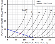
Please look to the first post schematic, there is 6N1P bias point: 150V, -1.7V bias and 340R cathode resistor, but this doesnt make sense. If you look at the curves the tube should conduct about 11mA with 150V and -1.7V. But this translates to cathode resistor of roughly 150 ohms.
I remember that I operated my 6N1P's with 300V B+ and 330R cathode resistors. Probably the bias voltage was larger than 1.7V --- because in my curent configuration, I have replaced the 330R cathode resistor with a green LED, giving a bias voltage of about 2.2V for balanced operation (~150V first anode).
Regards, Claas
Regards, Claas
Please look to the first post schematic, there is 6N1P bias point: 150V, -1.7V bias and 340R cathode resistor, but this doesnt make sense. If you look at the curves the tube should conduct about 11mA with 150V and -1.7V. But this translates to cathode resistor of roughly 150 ohms.
I checked. Broskie got it right. The value of Rk might come out to be 360R or 330R in real life, but 340R is really close.
Ebb = 300V
Rp = 30k
Rk = 340R
Vp = 150V
Vk = 1.7V
Ip = 5mA
See load line attached
Attachments
After many years since I started this thread, I'm about to fit a new set of iron to this amp - the ones that were in there always seemed to get quite hot, and I never liked that although they sounded great.
So anyway, all should work out except that the current ratings on the heater windings of the new transformer means that it would make sense to run 2 EL84 and 1 x 6N1P from one heater winding, and the same from the other heater winding. This means elevating the heater for the 6N1P phase splitter is not possible. But then the cathode should stay below 80V or so.
The datasheet for the 6N1P says max heater to cathode of 125V - so I shouldn't need to reference the heater to 1/4 B+ - or am I missing something here?
The original transformer was different which allowed the elevation of heaters easily.
Fran
Put one 0.1uf 400V cap from each end of each heater winding to ground. This will eliminate any hum thats present and you will not tie the filaments to any dc potential. Which means the tension will not appear or Im wrong?
Im using this in all of my amps and it seems to work good.
Im using this in all of my amps and it seems to work good.
Last edited:
- Home
- Amplifiers
- Tubes / Valves
- Unexpectedly good EL84 amp