Post 53
One of the subtle brilliances of the original circuit is that the resistors in the first two stages are matched. Any current increase in the first stage is matched by a current decrease in the second stage, and vice-versa. The same goes for the balanced output stage. This results in a constant current circuit, which keeps the power supply from being modulated by changing currents.
One of the subtle brilliances of the original circuit is that the resistors in the first two stages are matched. Any current increase in the first stage is matched by a current decrease in the second stage, and vice-versa. The same goes for the balanced output stage. This results in a constant current circuit, which keeps the power supply from being modulated by changing currents.
Hi, it seems to me that there is a typo in the schem of post #1. If bias is 13V the single catode resistor must be 200, not 400. Also, setting IP stage and concertina to get CDDA action through equal 30K resistors, you end with half the double triode drawing much more idle current than the other half, can it be a concern for tube life span, or it does not matter?
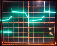
I got the amp assembled to a point where I can listen to it in stereo and I did some measurements as well. Seems to be working OK, sounds good and all the voltages are pretty much where they should be. The only thing that puzzles me is this weird distortion I get in the low frequency square waves. The picture is a 20Hz square wave. The lower trace is the input signal at about 1V and the upper is the output signal across an 8ohm resistor.
Can anyone say just by looking at the wave form what is causing the distortion? I get a slight bump on one side the sine wave from 20Hz to 80Hz and above that it's not visible anymore. The bump changes sides when I change the tubes around, so if I'm interpreting it right, it's just a slight mismatch between the tubes. Is the square wave distortion just how that mismatch looks like on the square wave of is there something else going on here?
Also, another thing I noticed is that when I turn my signal generator on, first the output square wave (say, 80Hz for example) is almost perfect, and after maybe half a second the distortion appears. Any ideas why there is such a delay there?
Attachments
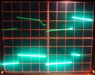
Here's a measurement from both the speaker output and right after the concertina. So the signal looks to be OK until it gets to the output stage.
I grounded pin 9 from the 6N1P but it didn't seem to make any difference.
Oh, and I noticed that at lower signal input levels the issue disappears completely.
I grounded pin 9 from the 6N1P but it didn't seem to make any difference.
Oh, and I noticed that at lower signal input levels the issue disappears completely.
Attachments
Last edited:
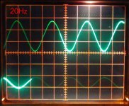
I swapped the tubes around so that I got two of the closest matched ones in one channel. The sine wave is virtually perfect down to 20Hz with an input signal of 1V. The square wave shows some distortion on one half of the wave form.
I'm certainly no expert but it doesn't seem like the issue is with the output iron and according to the manufacturer they should be OK down to 8Hz. They're Toroidy TGG-EL84PP. Since swapping the tubes around changes the situation significantly, to me it seems like it's an issue with slightly mismatched tubes, no?
I'm certainly no expert but it doesn't seem like the issue is with the output iron and according to the manufacturer they should be OK down to 8Hz. They're Toroidy TGG-EL84PP. Since swapping the tubes around changes the situation significantly, to me it seems like it's an issue with slightly mismatched tubes, no?
Attachments
You wrote earlier as follows:
Have you changed the anode resistor of the cathodyne to other value than the cathode resistor ? Both must be (in theory) equal.
Otherwise the output tubes get non-equal driving voltage, which in turn will cause increased THD.
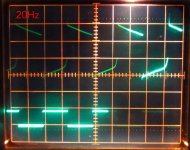
Concerning the wave form of 20 Hz square wave of a tube amplifier, it is very rare to even get clean 20 Hz sine response at 90...100 % of max. output power.
Only a OPT with very high primary inductance can perform well below, say 30...40 Hz at full power.
If your amplifier is 2 x EL84, try to observe with some 10 W, at what frequency the sine wave will be noticeably distorted (~5 % of THD).
If this happens below 30 Hz, you have got a very good performing output transformer.
I have tested Toroidy's TTG-EL84PP and that is a high grade product that may perform well down to 10...20 Hz.
Both halves of the 6N1P have a 30k resistor at the anode, but I'd get closer to nominal voltages by replacing one of those resistors with a slightly lower value resistor.
Have you changed the anode resistor of the cathodyne to other value than the cathode resistor ? Both must be (in theory) equal.
Otherwise the output tubes get non-equal driving voltage, which in turn will cause increased THD.
Concerning the wave form of 20 Hz square wave of a tube amplifier, it is very rare to even get clean 20 Hz sine response at 90...100 % of max. output power.
Only a OPT with very high primary inductance can perform well below, say 30...40 Hz at full power.
If your amplifier is 2 x EL84, try to observe with some 10 W, at what frequency the sine wave will be noticeably distorted (~5 % of THD).
If this happens below 30 Hz, you have got a very good performing output transformer.
I have tested Toroidy's TTG-EL84PP and that is a high grade product that may perform well down to 10...20 Hz.
The amp is assembled per the schematic except that the shared bias resistor is 180ohms instead of the 400ohms in the schematic and I also have the UL taps wired in through a toggle switch. All the measurements I've done are in triode mode.
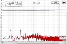
I've been trying to learn how to use Room EQ Wizard to measure amplifiers. I'm not at all sure I'm doing this right, but first I measured the input voltage at 1kHz right at the point where the sine wave starts clipping. The voltage is 1.9Vpp. At this input voltage I get 18Vpp across an 8.2ohm load resistor, which gives me pretty much spot on 5W if I've done my calculations right.
OK so now I go to REW and set the 1kHz output signal to 1.9Vpp or as close as I can and run the stepped sine wave measurement from 16Hz to 20kHz. This is the result I get. Look about right to you?
Attachments
Sorry for flooding the thread, but maybe someone else finds this useful (or maybe it's completely useless).
I've been messing with REW and I think I'm getting the hang of using the software. I did a bunch of measurements using my laptop and my Apogee Duet interface.
This is what I found. In triode mode I get:
-4.4W full power before clipping at 1kHz to an 8.2ohm dummy load.
-THD+N @ 1kHz at full power is 1.96% (mostly 3rd order harmonics)
-2.2W @ 1% THD+N (1kHz)
- -0.4dB @ 20Hz / -0.4dB @ 20kHz
In UL mode I get:
-10W full power before clipping @ 1kHz to an 8.2ohm dummy load
-THD+N @1kHz at full power is 3.73% (mostly 3rd order harmonics)
-3.4W @ 1% THD+N
- -1dB @ 20Hz / -0.5dB @ 20kHz
Let me know if you see something that doesn't make sense here. I'm only trying learn this stuff as I go.
As far as listening experiences go, it looks like I prefer the UL mode. I'll have to do a lot more listening to say for sure.
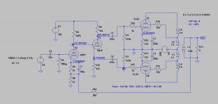
I made a modified (optimized) version and run some simulations with it.
It is better to have separate cathode resistors for output tubes.
A shared cathode resistor magnify the anode current unbalance, separate resistors reduce it.
This lessens the need to have well matched output tubes.
The gain of 6N1P is a bit low for this application. Therefore I modified the voltage amplifying stage to give maximum.
Also some 10 dB of GNFB is added. Now the performance is quite satisfactory. Sensitivity for full power is 0.92 Vrms.
Attachments
")
6N1P spec sheets show mu of about 30 to 35.
rp about 7.5k ohms (roughly)
gm about 4.5mA/V, although Svetlana/Sovtek claims 7.5mA/V (??)
http://www.radiovilag.hu/images/6N1P.pdf
http://www.mif.pg.gda.pl/homepages/frank/sheets/112/6/6N1P.pdf
So that first stage probably has stage gain of ca. 25X before gNFB. Just a wild guess.
rp about 7.5k ohms (roughly)
gm about 4.5mA/V, although Svetlana/Sovtek claims 7.5mA/V (??)
http://www.radiovilag.hu/images/6N1P.pdf
http://www.mif.pg.gda.pl/homepages/frank/sheets/112/6/6N1P.pdf
So that first stage probably has stage gain of ca. 25X before gNFB. Just a wild guess.
It is there. Just change the ".txt" extension to ".inc"
And , please upload your .asc.
This:
I modified my simulation according to that is in Mullard data sheet.
(Ub = 300 V, Rk = 270 ohms, etc.) With these values I got the same max. power, 11 W,
same idle current for EL84, 40 mA, same drive (Vin rms), 16 V.
THD is not that straightforward to compare. In LT Spice with tube, THD is some "sketchy" number.
And , please upload your .asc.
This:
wonder how you got only 0,29% THD with output power 14,6W ? In my simulations I get 1% with 10W output power.
I modified my simulation according to that is in Mullard data sheet.
(Ub = 300 V, Rk = 270 ohms, etc.) With these values I got the same max. power, 11 W,
same idle current for EL84, 40 mA, same drive (Vin rms), 16 V.
THD is not that straightforward to compare. In LT Spice with tube, THD is some "sketchy" number.
Last edited:
- Home
- Amplifiers
- Tubes / Valves
- Unexpectedly good EL84 amp