Hi,
here are som pics from the Amp and the measured values. It is something wrong with my pics upload to the forumserver. I use an exterenal hoster which belong to a german electronic freak forum.
Pic.1

Input power at full output, but the mains voltage drop to 215V, thats bad. With 215V I cannot testing the max. output of the amp. I changed the power supply by inserting a 400 to 230V transformer. The transformes is fed from 2 phases. Now I can draw 25A without major voltage drop. The cable from the house to my workshop is 50m apart.
Pic.2

This one show the plate voltage at no input signal, impressive 2700V!!
Pic. 3

This one show the Idle current of the output valves. 160mV at the 0,51 ohms shunt resistor means 313mA include the screen current.
Pic. 4

This is the huge power transformer for the mains supply. I came across with it on a ham rallye the other day , its a heavy beast its weight is abt 60kg also 120 pounds.
pic.5

This one show the mains voltage with the amp off. The amp is the only device behind the trafo.
Pic.6

This is the output voltage across the 8 Ohm dummy load, 1kHz signal.
Pic.7

This here ist the output voltage at the prim. side of the opt. it show 2,5kVac rms.
Pic 8

The amp is on, but without signal.
Pic.9

The chaotic setup
Pic.10

This oscillogram show the kathode current of one of the output valves. 8,2V at 3,3 ohms
Pic.11

Pic.12

pic 11 + 12 show both the signal at dummy load (upper) and at the kath. of the driver (EL34) (lower)
Pic.13

View at the amp modul.
14

Test sockets
Pic.15

..more test sockets
Pic.16

The huge HV Capacitor 6µF /6000V
Pic.17

The homebrewed C-core aux power transformer.
We had a soundcheck yesterday with 1/5 output power and 2 speaker wich can handle 400W total . 1/5 means the most output going into the dummy load. I cannot turn up to the clipping level .
The sound is uncredible and not to discribe. Better should say a live rock Concert in my workshop. Standing in front of a pounding drumset and grooving bass....
73
Wolfgang
Hi folks,
nearly three months going into the land and many things happend, some good , some bad. The bad one was I blew the opt. oh jes it was very bad. Loads of hours unnecessary work because of one destracted second. A unnoticed short of a test lead against ground raise the anode current to it maximum. Just before I noticed the bright shine of the tube, sparks flowing and a terrible sizzling noise followed by a loud bang trip the cb of the power supply....
Ok the day were ruined, but I will not giving up, never. So next day I remove the opt from the chassis and start unwind the coil. I use the winding machine to save the wire on empty reels. I came after the 5th layer to the burned part. The Insulation foil was melt and the +b found its way to the the grounded screen foil , which is made with one winding copper foil.
It need the evenings of 7 days to fix the whole thing. After this accident I install a HV fuse , 1,6A 3000V . A sense Circuit in the Power supply which turn it off in case of overload.
The good thig, the output tube , GU81 survive this short!! Remember, the outputs run with 2500V , and the supply can easily deliver 2A current.
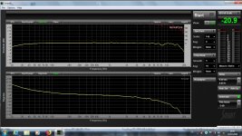
After all ist repaired I made the test with the nfb. The test setup with a Computer audio mesurement program show the frequency / phase diagram. Whith the help of it I tweak the nfb to the optimum.
The data changed al little from that what I show her before. The maximum otput is 1600W at 7% THD. At 1500 ist it 5% THD. and 2,5% at 700W.
But the more important thing than a low THD ist the phase shift.
The 3db points are at 20Hz and 15kHz.
It seems I can finally put the panels on and put it in a rack with its power unit. The audible test without dummy load shoud come up next. But not at my place. I own 6 JBL Control 12sr and 2 JBL 4870 homebrew with original JBL Components.
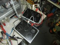
The right pic show the bode-diagram and the left one the setup for tweaking the nfb.
73 Wolfgang
nearly three months going into the land and many things happend, some good , some bad. The bad one was I blew the opt. oh jes it was very bad. Loads of hours unnecessary work because of one destracted second. A unnoticed short of a test lead against ground raise the anode current to it maximum. Just before I noticed the bright shine of the tube, sparks flowing and a terrible sizzling noise followed by a loud bang trip the cb of the power supply...
. Ok the day were ruined, but I will not giving up, never. So next day I remove the opt from the chassis and start unwind the coil. I use the winding machine to save the wire on empty reels. I came after the 5th layer to the burned part. The Insulation foil was melt and the +b found its way to the the grounded screen foil , which is made with one winding copper foil.
It need the evenings of 7 days to fix the whole thing. After this accident I install a HV fuse , 1,6A 3000V . A sense Circuit in the Power supply which turn it off in case of overload.
The good thig, the output tube , GU81 survive this short!! Remember, the outputs run with 2500V , and the supply can easily deliver 2A current.
After all ist repaired I made the test with the nfb. The test setup with a Computer audio mesurement program show the frequency / phase diagram. Whith the help of it I tweak the nfb to the optimum.
The data changed al little from that what I show her before. The maximum otput is 1600W at 7% THD. At 1500 ist it 5% THD. and 2,5% at 700W.
But the more important thing than a low THD ist the phase shift.
The 3db points are at 20Hz and 15kHz.
It seems I can finally put the panels on and put it in a rack with its power unit. The audible test without dummy load shoud come up next. But not at my place. I own 6 JBL Control 12sr and 2 JBL 4870 homebrew with original JBL Components.
The right pic show the bode-diagram and the left one the setup for tweaking the nfb.
73 Wolfgang
Attachments
Here we go again.......unfortunately my harddrive crashed years ago and lost that russian article....

ГУ-81 LINK1
ГУ-81 LINK2
ГУ-81 LINK3
Regards,
Yugovitz

Hi, have you got a englisch or german version of the text.
73
Wolfgang
Google Translate does a reasonably good job with the translation.
Yep...Google Translate is a nice tool...!

Regards,
Yugovitz
Hi,
Well made, a great work, respect!! What size and weight does the opt got?
73
Wolfgang
...done.Google Translate does a reasonably good job with the translation.
Well made, a great work, respect!! What size and weight does the opt got?
73
Wolfgang
Keep us updated.

Hi,
I would be interested in a schematic for this amp with GU81. Thanks
Hi,
Do you mean the schematics of my amp?
I can put them here into the thread. But I have convert them first into jpg or pdf. At the moment I have them only as "S-Plan" , a schematic drawing program.
73
Wolfgang
I am interested in the schematic for your GU81 amp. thanks in advance.
Do you mean the schematics of my amp?
I can put them here into the thread. But I have convert them first into jpg or pdf. At the moment I have them only as "S-Plan" , a schematic drawing program.
73
Wolfgang
@Funker: Glad to hear from you again, Wolfgang
Best regards!
Hi Uwe,
thanks a lot. The fine weather conditions here in the north germany force me to set the priority to my Solar Power project at my home. I got a new storage batteries ( 18kWh Li-ion packs) and a rack cabinet for the inverters.
So all my amp projects have to wait a little while.
73
Wolfgang
- Home
- Amplifiers
- Tubes / Valves
- GU-81m tube amp schematics???