mashaffer,
I guessed what you were saying, but I wanted to be sure that some who only read the thread at the end postings would understand that.
I also re-edited my post, just after you posted.
I love this forum.
I have to call my son, and ask him how to turn my "intelligent" spell checker OFF!
I have found that Spell Checkers are only helpful on October 31, Halloween.
Think about that for a Spell.
In the railway industry, spark gaps with carbon disks are used to protect lines. Some are not sealed. Railroad Lightning Arrestors
There are numerous other spark gaps and GDTs used for industrial applications. Unless you work in these industries you would never see them. In you are a HV hobbyist, the rotary spark gap is quite common.
How silly from me I did not think of those and instead suggested much simpler solutions
My bad
Yep, Autocorrect is the spawn of Santa.")
I ducking hate autocorrect...
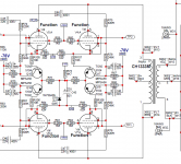
I came across an interesting implementation. The Traynor YBA-200 bass amp uses a PNP transistor that acts as a switch to vary the fixed bias voltage according to the cathode voltage. As the cathode voltage rises above ~4V, the PNP starts to turn off, dropping the fixed bias more negative.
Attachments
Gentlemen,
Sorry to revive an old thread, but it is directly relevant to a question I have.
I am designing my first tube amplifier. It is a 3W 6A5G SET design, will have 8ohm speaker and headphone outputs.
I plan to have a switch to change from speaker to headphone out. Headphones used will be 300ohm primarily, so I will have a 9ohm resistor in parallel with the headphone output to give the OPT a reasonable load.
For open circuit protection, it was suggested to me to permanently place a 470ohm resistor across the OPT secondary. Is that an effective solution to protect the OPT when the switch is turned to speaker output and also when the switch is turned to headphone output with the 9ohm resistors in parallel? Thanks.
Post a new thread dedicated to your current problem.Gentlemen,
Sorry to revive an old thread, but it is directly relevant to a question I have.
L0rdGwyn, you may find what you are looking for already in this (long) thread - I suggest posts 29 and 71.
Thank you trobbins, post #71 answers my question, much appreciated.
Keep in mind that a fuse rated for use as a line fuse (i.e. the 120V AC 60Hz line) IS NOT SAFE to use in a HV DC line. In its intended use, the fuse, when overloaded, will cleanly blow and safely open the circuit. That same fuse used in a B+ setting for tubes will, when overloaded, open, but because of the HV DC, the metal link will vaporize and the vapor itself will conduct (due to the HV DC and the fact that unlike AC, there is no zero voltage crossing to extinguish an arc), and you could end up with a fire. Don't use those fuses for DC.
Or use a longer fuse than usual and derate it. Even then, for the average current draw with a 300V tube amp supply, the largest arc I've seen was about 2mm. a 20mm fuse will quench it unless the supply can provide SERIOUS power. Just my experience. Yours might be different.
I’ve blown 250 mA fuses on a 400 volt supply before - with only the potential for a 3 amp fault current. 135 ohms of series resistance. It made a VERY LOUD kabang, and there was vaporized metal covering the entire inside of the glass fuse. It did open circuit. I’m not sure it could always be trusted to do so. It was on a screen voltage OVP circuit, so even if it failed short the crowbar still would do its job. But it would still be a hazard. I added a slow blow primary fuse to ensure that something would eventually open besides the transformer or rectifiers. I though something blew up during the test, because I was not expecting the fuse blow to be THAT loud.
For fuse stress there is the issue of fault current level, and series inductance.
For industrial fuses with DC it is characterised by an L/R ratio. If there is more inductance in the fault current path then that is harder on the fuse to extinguish its internal arc.
If there is a high instantaneous peak of current, like a capacitor discharging through a low resistance, then the fuse element pretty much instantly vaporises (an adiabatic I2t event), where as if the fault current is lowish, then the fuse element just cooks until it weakens enough to fail, but at that time the available energy in a bulk capacitor may have sagged quite a lot.
It all depends ........
Last edited:
- Home
- Amplifiers
- Tubes / Valves
- Tube output protection