Hello All and Happy New Year.
I'm posting my latest creation for some advice.
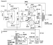
I'm playing this amp now and it sounds very good but I would like more bass.
I dont have a pre-amp with controls just feeding it with "line out" from my CD player. I have read some treads that suggest that the 1000 ohm resistor in the NFB may cause oscillation and should be changed. So far I have not seen or heard any oscillation. Which way should I go with the resistor/capacitor values to get a little more bass?
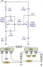
I could build a passive tone control to put at the input. Any Ideas about this?
I'm posting my latest creation for some advice.
I'm playing this amp now and it sounds very good but I would like more bass.
I dont have a pre-amp with controls just feeding it with "line out" from my CD player. I have read some treads that suggest that the 1000 ohm resistor in the NFB may cause oscillation and should be changed. So far I have not seen or heard any oscillation. Which way should I go with the resistor/capacitor values to get a little more bass?
I could build a passive tone control to put at the input. Any Ideas about this?
Attachments
Hi,
I would do the following:
Install a 470 Ohm resistor to bias the 12ax7 (in parallel with the 50uF cap)
Change the 1000 Ohms resistor for a 3K resistor or a 5K trimmer to be able to adjust the feedback. Once you find the sweet spot remove the trimmer for a fixed resistor. Bypassed it with a 270 pf cap. Small mod that may or may not solve your bass problems but worth a try. Think it would improve it.
Increasing the 1K resistor will reduce the feedback, and so increase the gain and output impedance. This may cause a bass peak at the loudspeaker bass resonance - sometimes known as "one note bass".
Changing the 1K resisor will also change the bias for the 12AX7, as in this design the resistor has two functions: feedback and cathode bias. Hence the need for a separate bias resistor if the 1K is increased.
Changing the 1K resisor will also change the bias for the 12AX7, as in this design the resistor has two functions: feedback and cathode bias. Hence the need for a separate bias resistor if the 1K is increased.
Forgot to say that I'd also change the power supply to silicon diodes and at least 100uF caps but you'll have to adjust the B+ and I don't see how (don't like the idea of increasing the resistance). Maybe a regulated supply? As you can imagine this mod isn't as cheap and easy as the first one. ")
- Status
- This old topic is closed. If you want to reopen this topic, contact a moderator using the "Report Post" button.