Hi, this is an old thread but do have the schematic, i just need a single pl519
I have build a amp based on the Synola schematics. The distortion that you are hearing is very distinct and it's origin is in the tube that drives the screen grid on the PL519. When I first build the Amp I used a paralleled 8CG7 (kinda 6SN7 tube). This tube wasn't able to supply the current needed for screen drive and started distorting at aprox. 1W output power.
I have replaced the 8CG7 with a EL84 and now this limitation, and it's ugly distortion, is gone.
You can find the schematics of the amp here: 404 - Kan bestand of map niet vinden.
One side note: This amplifier sounds so incredibly good that one MUST build it. I am using it to drive a pair of Jamo Concert 11's. It has more than enough power for these speakers and the soundstage is unbelievable realalistic! This amp will blow away 30K+ commercial amps!
Hi,
Here is the first of two messages I got from lechuk regarding the EL509 Se amp.
"It's been about three or four years ago that I was working on that design, it was stored on a server that I do not longer have so I'm afraid that the schematics are gone.
I did however build and analysed it extensively and I also experimented with two EL509's per channel, so I kind of know the circuit pretty well. It's basically a class A2 amplifier, but instead of having to bother with grid current it is screen current that you must consider. The main flaw of the Synola design is that the cathode follower that is used cannot sink enough current which causes nasty distortion at mild power levels. Another flaw is the first gain stage, it's a high mu grounded grid design which reduces power levels at higher frequencies due to high input capacitance (mr Miller).
If you have already bought the iron then I can help you out with a proper design that should work well. If you haven't bought them yet I would strongly suggest not to build this as a single ended amplifier but as a push-pull amplifier instead. The quality of the sound from the single ended design is fine on my Jamo D870 speakers, but it lacks output power because (I always find myself turning up the volume") I prefer the push-pull version that I've designed. It's a very simple three stage design that I am using at this moment, and which I am also developing in my limited spare time.
I prefer the push-pull version that I've designed. It's a very simple three stage design that I am using at this moment, and which I am also developing in my limited spare time.
If you already have bought the parts then please let me know the specifications. If you just want to build/copy an existing design I can draw it up for you in a few weeks. Or I can help you with drawing up a design of your own if you would like to learn and fully understand the amplifier."
Here is the first of two messages I got from lechuk regarding the EL509 Se amp.
"It's been about three or four years ago that I was working on that design, it was stored on a server that I do not longer have so I'm afraid that the schematics are gone.
I did however build and analysed it extensively and I also experimented with two EL509's per channel, so I kind of know the circuit pretty well. It's basically a class A2 amplifier, but instead of having to bother with grid current it is screen current that you must consider. The main flaw of the Synola design is that the cathode follower that is used cannot sink enough current which causes nasty distortion at mild power levels. Another flaw is the first gain stage, it's a high mu grounded grid design which reduces power levels at higher frequencies due to high input capacitance (mr Miller).
If you have already bought the iron then I can help you out with a proper design that should work well. If you haven't bought them yet I would strongly suggest not to build this as a single ended amplifier but as a push-pull amplifier instead. The quality of the sound from the single ended design is fine on my Jamo D870 speakers, but it lacks output power because (I always find myself turning up the volume
I prefer the push-pull version that I've designed. It's a very simple three stage design that I am using at this moment, and which I am also developing in my limited spare time.If you already have bought the parts then please let me know the specifications. If you just want to build/copy an existing design I can draw it up for you in a few weeks. Or I can help you with drawing up a design of your own if you would like to learn and fully understand the amplifier."
Here's the second message.
"The 6P45S is very nice tube, it can handle slightly more plate dissipation in comparison to a EL509 and their availability in the EU is also outstanding!
Since you already have the output transformers and efficient speakers I would suggest to use them and build a single ended amplifier. I have found with paralleling the output tubes that it smears the sound. The tubes need different bias settings and are not conducting the same amount of current at a given signal level. A single 6P45S into 5K should work very well.
To keep it simple I will divide the amplifier into four sections:
1) power supply
2) output stage
3) driver stage
4) gain stage
1) I would keep the power supply simple and straight forward. A GZ34 can be used for rectification, but you can also use normal diodes like the U4007 and BYV228 types. Use a CLC configuration for the power supply. If you search for PSUDesigner from Duncan Amps you can work out the proper values for the C's and L. I have used an L with 10H/75 ohms and C's of 220u for use with normal diodes. Also you should damp the rectifier with enough resistance to match it with the power transformer. Tube datasheets describe the minimum required impedance, for normal diodes you should look at the current through the diodes in PSUDesigner.
Keep in mind that you can bias the 6P45S up to 110mA@400 volts, expect about 3 to 5mA for the gain stage and up to 25mA of screen current.
2) The output stage will then be a single 6P45S working into 5K at 350/400 volts. Grid 1 needs a negative voltage of about 40volts, G2 will be around 160-180 volts positive.
3) The driver can be a tube cathode follower or a FET source follower. I would personally go for a cathode follower because most FETs have high gate capacitance, and we need a high gain stage to drive it. A EL84/6BQ5 in triode mode works very good, or you can use a ECC99 (a single triode can drive the screen). The cathode follower is directly attached to the screen grid of the 6P45S, this configuration can be seen as deep class A2 because there is grid current all the time. Do not apply the resistor to ground, or keep it at a really high value. The resistor value used in the Synola design is way too low and loads the cathode follower heavily. Besides the cathode follower can see ground through the screen grid of the 6P45S thus a resistor is not needed at all. The grid of the cathode follower should be protected during warm up with a diode, the diode will bias off when the tubes are conducting.
4) The gain stage will need to provide high gain for the screen grid of the output stage. The screen grid is very sensitive, but not as sensitive as the first grid so it's needs more gain than usual. I would suggest to use either a pentode (D3a, EF86 or 6SL7 for example) or a cascaded topology with two medium mu triodes. I would suggest to go with a cascaded topology, you can use tubes like the 12AU7/ECC82/6DJ8/ECC88/E88CC/ECC99/6CG7/6SN7 and other medium mu triodes.
I'm guessing the small parts like capacitors and resistors should not be a problem for you to get your hands on. Do have the possibility to have custom power transformers produced or do you have choose from an existing product range (if so, which manufacturer)?
Do you want independent power supplies for each channel? Tube or diode rectified?
Do you have medium mu triodes or pentodes, or do you have a specific small signal tube that you want to use?
Do you want to build the amplifier on a printed circuit board or do you want to hardwire the amplifier?
Do you have a power transformer on the bench as well that you can temporarily use to quickly build a test amplifier so you can judge the quality of the sound before you invest in expensive parts?
Best regards"
If you are using a tv tube output then may as well drive it with a tv tube. There area lot f triode pentode combos that have a frame grid pentode IE 6jt8 6kv8 etc. No worries I got scads of them at under $1.00. The pentode can be used triode connected c.f. trandcondtance is 20k at around 15ma. Impedance is 50 ohms; which eliminates any issues with screen grid drive.
I got a quad and ran them on my Sofia. It's a sweep tube; the spec is BS. Looking at the spec sheet they operate the tube at 175v max and the knee is around 850mA.
Could you be more specific, please. A quad of what? And what’s unexpected in you Sofia analysis. EL509s were designed as TV sweep tubes; not much wrong with that.
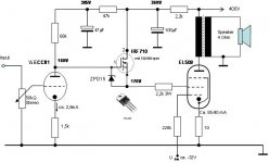
I found the schematic, if this is what you needed...
I was hoping someone had the schematic that was externally referenced in post #33. The original Synola schematic that Lampie519 posted (thanks) is readily available on the Web, the “improved” version that lechuck designed and referenced in #33 is of interest.
Thanks to Mush for posting the correspondence with lechuck. It helps, but a schematic would be a great addition.
Hi,
Here is the first of two messages I got from lechuk regarding the EL509 Se amp.
“<snip>
If you have already bought the iron then I can help you out with a proper design that should work well. If you haven't bought them yet I would strongly suggest not to build this as a single ended amplifier but as a push-pull amplifier instead."
I wonder if we could encourage lechuk to say more about the PP design he ended up with after all the experimentation?
A quad of what ??I got a quad and ran them on my Sofia. It's a sweep tube; the spec is BS. Looking at the spec sheet they operate the tube at 175v max and the knee is around 850mA.
Joy!!
Thanks for your post. Some joy but not the big one yet 😜
What is missing is the referenced schematic in post #33, that was on a off-line server that is now gone, by the author’s admission.
I cleaned it a little to be less confusing. The previous schematic still had the ECC82 on it.
Wonderful and thank you, Mush! I will try it when I get down my list. Thanks again.
I cleaned it a little to be less confusing. The previous schematic still had the ECC82 on it.
Wonderful and thank you, Mush! I will try it when I get down my list. Thanks again.
Joy!!
Except I would move the current limiting resistor up, to the drain.
I cleaned it a little to be less confusing. The previous schematic still had the ECC82 on it.
Wonderful and thank you, Mush! I will try it when I get down my list. Thanks again.
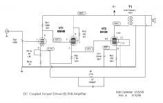
Bob Danielak Screen Driven PL519 EL509 6KG6 or 859 Tim de Paravicini
Hi, I was looking at building this Amp by Bob Danielak screen driven EL519 but have a 275v 300vA transformer = 388v DC
Or a 325v 300vA = 459 v DC
Could go higher Plate Voltage and lower current like the Tim de Paravicini 859 amp for a bit more power out
Pretty close to the 400v required but see a few comments re its actual available power out on a 5K load of 10 watts ?
Am pretty sure the 859 is 5K Primary
Has anyone build Bobs design recently and have any distortion figures at 1 watt and full power?
Thanks
Attachments
- Status
- This old topic is closed. If you want to reopen this topic, contact a moderator using the "Report Post" button.
- Home
- Amplifiers
- Tubes / Valves
- EL509 (JJ) or PL519?