Please note!
If you build this circuit it produces 300V-400V Dc and can be lethal! Put a 1Meg resistor across the output to drain the HT at power off! I also used a current inrush suppressor of 10 Ohm at 10A to give a slight voltage drop from the laptop PSU and improve the sound!(Soft start)
Regards
M. Gregg
If you build this circuit it produces 300V-400V Dc and can be lethal! Put a 1Meg resistor across the output to drain the HT at power off! I also used a current inrush suppressor of 10 Ohm at 10A to give a slight voltage drop from the laptop PSU and improve the sound!(Soft start)
Regards
M. Gregg
EM80's
Link to information. For those that like to experiment!
Values and pinout need changing for EM80.
The Site for Electronics, Microcontroller, Tubes, Forum, PCB, Circuits, Onlineshop
")
Regards
M. Gregg
Link to information. For those that like to experiment!
Values and pinout need changing for EM80.
The Site for Electronics, Microcontroller, Tubes, Forum, PCB, Circuits, Onlineshop
Regards
M. Gregg
OK.
I have "created in p. point and converted to jpeg" the input selector section schematic.
I must admit I don't know why anyone would use a rotary switch when you can position a single push button any where on the chassis and have the relay board next to the phono socket inputs. The 18K for the reset is not critical, however if the value is to high or low it will effect the current drain from the chip or not allow a "0" for the count. The 0.1uf from supply to reset ensures that the selector always starts at output "0". It is easy to modify for as many inputs as required!You could use output "0" as mute at start and move the inputs to output 1,2,3,4 etc.
Regards
M. Gregg
Thats nice! Thanks.
Nice project
I really like the multi-coloured prism for input identification
Thanks for the links on the little inverter supply. I wish I had seen them when I was building some nixie clocks. Its amazing how such a simple thing as an inverter can become perplexing. I was trying to reverse engineer a camera flash inverter to save space. It let the smoke out The design you linked to would have been perfect.
Cheers Matt.
I really like the multi-coloured prism for input identification
Thanks for the links on the little inverter supply. I wish I had seen them when I was building some nixie clocks. Its amazing how such a simple thing as an inverter can become perplexing. I was trying to reverse engineer a camera flash inverter to save space. It let the smoke out
The design you linked to would have been perfect.Cheers Matt.
Nice project
I really like the multi-coloured prism for input identification
Thanks for the links on the little inverter supply. I wish I had seen them when I was building some nixie clocks. Its amazing how such a simple thing as an inverter can become perplexing. I was trying to reverse engineer a camera flash inverter to save space. It let the smoke out
Cheers Matt.
Thank's Matt.
Did you ever get the clocks working
I will post other info as I put it to Jpeg.
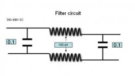
Here is the filter that fits between the Inverter and the Maida regulator. Similar circuits have been used in other posts!
Regards
M. Gregg
Attachments
 Yeh I got the prototype working. I went through two itterations of simple inverter, but was never really happy with it, I just lashed up the simple inverter you use and it works a treat will use it for something I have on the to do list.
The prototype of my clocks was given away to a very nice fellow who gave me a HP334 for nothing
The later versions and the prototype ended up using an IC based design. I actually built one up but found these(usual disclaimer):
6 digits Nixie Clock prototype f
For the price its hardly worth messing about making it. chuck a couple of diodes in the 5V regs ground and maybe a heatsink and you have a heater supply as well, or a 6V reg and a germanium diode if you are set on 6.3V. Its fairly easy to up the output current to.
Cheers Matt.
Last edited:
Hi M Gregg
I have only just had the time to get on with my pre-amp due to starting a new job
Ok, when I put the input selector together on the breadboard it worked fine, now I've put it together on a PCB it won't work I have looked at it some much that my brain is fried!!! Can you have a look at the link below and let me know if you can spot any howlers on my PCB???
http://http://s1155.photobucket.com/albums/p551/Dagwood72/
Cheers
Dagwood
I have only just had the time to get on with my pre-amp due to starting a new job
Ok, when I put the input selector together on the breadboard it worked fine, now I've put it together on a PCB it won't work
I have looked at it some much that my brain is fried!!! Can you have a look at the link below and let me know if you can spot any howlers on my PCB???http://http://s1155.photobucket.com/albums/p551/Dagwood72/
Cheers
Dagwood
Bugga
Just noticed this...!!!!
Man, I missed your exsit by days.... all the best with your break Gregg, you will be missed
Ok guys, what am I missing on this layout????? I have added M Greggs original design
to my photo album.... just can't see what I'm missing
Pictures by Dagwood72 - Photobucket
Just noticed this...!!!!
__________________Bye for now!
Ok,
I think I have done what I wanted for now so have fun and keep building.
Had a great time here, it's time to move on.
Regards
M. Gregg
Man, I missed your exsit by days.... all the best with your break Gregg, you will be missed
Ok guys, what am I missing on this layout????? I have added M Greggs original design
to my photo album.... just can't see what I'm missing
Pictures by Dagwood72 - Photobucket
Hi M Gregg
I have only just had the time to get on with my pre-amp due to starting a new job
Ok, when I put the input selector together on the breadboard it worked fine, now I've put it together on a PCB it won't work
http://http://s1155.photobucket.com/albums/p551/Dagwood72/
Cheers
Dagwood
I don't know, guess I must say something..LOL
If your circuit and layout is correct then you may have some cap coupling because of layout. Possible problems could be no input from the 4093. ie no switching.
To check this make a simple probe with a 1K resistor and a LED test for input to pin 14 of 4017.
Other cause from coupling can be the balance set by the 18K an the 0.1 cap on the reset out of balance. So to test this reduce the 18K to 10K and test. if the value gets to low the auto reset will not work. If its to high the counter will remain in reset and will not count.
The only other thing could be the enable which should be at Gnd.
I will watch to see if you are OK. I can't leave you to struggle.
Regards
M. Gregg
I built the power supply (just curious as I have no real application) and got lousy efficiency (17%).
So, after several attempts to tune it, I changed to a Royer topology. I'm up to 45% with 250V and 30mA out. I can crank it to 400V and 50mA with 41% efficiency.
I'm using FET with the Royer.
I've tweaked it about as well as I can ( including operating frequency, snubber values, etc). Right now it is running off a wall wart supplying 8.35V at 2A. Using a power supply with 13V it will draw 3A with the same 8.2K load, but deliver just over 400V.
Has anyone gotten better efficiency?
I suspect the core used has a lot to do with the design, and I am using an unknown core. I could use (Steward 615-867-4100) but it is shorter and would be more difficult to wind. On top of that I don't know that/if it would work better.
The winding is dual 14T primary, 400T secondary, 28T Tertiary for gate drive.
Last edited:
I built the power supply (just curious as I have no real application) and got lousy efficiency (17%).
So, after several attempts to tune it, I changed to a Royer topology. I'm up to 45% with 250V and 30mA out. I can crank it to 400V and 50mA with 41% efficiency.
I'm using FET with the Royer.
I've tweaked it about as well as I can ( including operating frequency, snubber values, etc). Right now it is running off a wall wart supplying 8.35V at 2A. Using a power supply with 13V it will draw 3A with the same 8.2K load, but deliver just over 400V.
Has anyone gotten better efficiency?
I suspect the core used has a lot to do with the design, and I am using an unknown core. I could use (Steward 615-867-4100) but it is shorter and would be more difficult to wind. On top of that I don't know that/if it would work better.
The winding is dual 14T primary, 400T secondary, 28T Tertiary for gate drive.
I guess you looked at the other links just for interest:
Photos Section
Jan's Inverter Instructions
This is only part of the fun, you have to power some tubes and get it sounding "good".
I chose ECC88 just because they are supposed to be good but guess what..the heater current is higher than garden 83..81 ect.The inital problem I set myself was, I can only have pure DC at a single low voltage ie laptop psu, It must power an Aikido line stage with its quirky top tube heater /cathode requirements, and two EM80s + selector. So how do you keep the HT off the dc low voltage and lift the heaters?
(Then again do you need to?). I found that most people seem to avoid the inverter because of the Tx required..so this just uses a large ferrite bead..just for fun of course A fun project..with many unusual problems..just for fun..and because it gets you thinking..Its still working with no problems since the build.
Regards
M. Gregg
Last edited:
Yes, I looked at those. The initial design was using a ferrite rod, and I had several so I used the one which was most physically adaptable.
He reports good efficiency with a pot-core, but I don't have any on hand.
I suspect my core is the problem since ferrite cores can vary considerably in their properties and this one has no part number I can look up.
I may try disassembling a transformer for the cores by boiling as is suggested on Jan's Inverter Instructions.
Yes, I looked at those. The initial design was using a ferrite rod, and I had several so I used the one which was most physically adaptable.
He reports good efficiency with a pot-core, but I don't have any on hand.
I suspect my core is the problem since ferrite cores can vary considerably in their properties and this one has no part number I can look up.
I may try disassembling a transformer for the cores by boiling as is suggested on Jan's Inverter Instructions.
Please post your inverter schematic,
The interest with this kind of build is you can mix and match and build all kinds of projects..OK the HT is dangerous but no mains..
Hopfully you will build an inverter project just for fun (dual channel)...getting the ripple out of the B+ and getting good sound is interesting..
Regards
M. Gregg
Ripple is in the audio range (135Hz IIRC).
FETs were STW9NB80.
I found C6 to be more effective in controlling the frequency than C1, but also found it would not oscillate between 30KHz and 1MHz. At least I could not find a cap that would work in that range. As I came down from 1MHz, it jumped to around 27KHz.
Power dissipation at 1MHz was excessive and at 3MHz it only put out 24V.
Oscillation frequency is load dependent.
Operation at 400V out 50mA load, resulted in a 50degree F rise in the transformer temp. At 250V out 30mA load the temp rise was only 20degrees F.
Attachments
Hi M Gregg
I have only just had the time to get on with my pre-amp due to starting a new job
Ok, when I put the input selector together on the breadboard it worked fine, now I've put it together on a PCB it won't work
http://http://s1155.photobucket.com/albums/p551/Dagwood72/
Cheers
Dagwood
Are you up and running?
Regards
M. Gregg
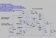
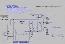
This is the updated schematic as of tonight. I use the pot to set the bias current for minimum. This corresponds to the maximum output.
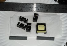
The second is a photo of the cores I took apart tonight. I tried boiling them in water to no avail. I finally had to heat them in an oil bath to almost 300C before they would separate. Needless to say, this destroyed the plastic coil forms so I will have to bust two more to recover the coil forms from them.
Fortunately I get them for free so I only have a little time in removing them from boards as an investment. I suspect they will be too small for the number of turns i need to wind, however they were rated at 24W for the 120/240 to 24vdc switcher they came from. I think it operated at 400KHz.
In addition there are two of the cylindrical ferrite forms I used in the original switcher.
Attachments
This is the updated schematic as of tonight. I use the pot to set the bias current for minimum. This corresponds to the maximum output.
The second is a photo of the cores I took apart tonight. I tried boiling them in water to no avail. I finally had to heat them in an oil bath to almost 300C before they would separate. Needless to say, this destroyed the plastic coil forms so I will have to bust two more to recover the coil forms from them.
Fortunately I get them for free so I only have a little time in removing them from boards as an investment. I suspect they will be too small for the number of turns i need to wind, however they were rated at 24W for the 120/240 to 24vdc switcher they came from. I think it operated at 400KHz.
In addition there are two of the cylindrical ferrite forms I used in the original switcher.
Thank's for posting the schematic,
Yes I tried to use various switcher cores, I found they tend to be fragile and break at the corners. A real pain to strip. Then you need the mylar tape and winding with any magnet wire over size is almost impossible.. I have 350-400V from the ferrite bead and just the two windings..
...Then again I found the the experiment very interesting and realy enjoyed this project..I was going to try a tube preamp stage for the car just for fun never got around to it..headphone amp...etc..LOL...Mini tube amp for the PC...or driver board..nixie clock..OK some of it has been done, however the journey is great fun! The trick is to get it sounding "Good"...
Just another few thoughts nixie clock for the car or motor bike HP amp,EM80 car VU meter ...LOL
Regards
M. Gregg
Last edited:
- Status
- This old topic is closed. If you want to reopen this topic, contact a moderator using the "Report Post" button.
- Home
- Amplifiers
- Tubes / Valves
- Strip board project completed.