Folks,
I figured I'd share... Transformers are not exactly rocket science, but some people seem to be a little intimidated by them.
I have an Antek 2T350 that I intend to use for a project involving 5AR4 rectifiers. These rectifiers have a 5 V filament. The trafo provides 6.3 V. What to do...
Option #1: Insert a 0.68 ohm resistor in series with the 5AR4 filament. This drops 1.3 V across the resistor and voila, 5.0 V across the filament. However, it also dissipates about 2.5 W in the resistor which will need to be gotten rid of.
Option #2: Unwind the secondary a little bit to change the turns ratio from 120:6.3 to 120:5.
I opted for the latter on this project. I counted 21 turns on the secondary. So a little back of the envelope math:
6.3/21 = 0.3 V per turn
5/0.3 = 16.7 turns
So to get a 5.0 V winding, I'd have to make a 16.7 turn secondary. 17 turns aught to be close enough... So if I remove four turns from the existing secondary, the voltage should drop to 5 V (maybe slightly higher). So I set out to remove four turns...
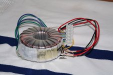
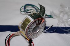
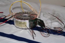
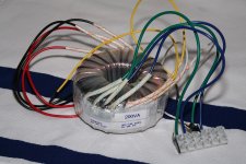
It's quite straight forward. The tape end of the plastic film wrapped around the transformer is found and the tape is removed. Then the plastic film is carefully unwound enough to expose the secondary connections. Taking care not to nick the windings, an exacto/utility knife is used to cut back the adhesive tape wrapped around the core. Note how the ends of the two secondary windings are interleaved between a piece of card stock to ensure that they don't short out. Pay attention to the sequence of the wires. I removed two turns from each end of each winding. The turns are actually bunched up slightly at the termination point, so I could do this and still have the secondary evenly spaced across the circumference of the core. With the now 17-turn secondary, I measured the secondary voltage. I loaded the secondary with a 5AR4 rectifier for this measurement. At 115 V input, I measured 5.0 V. At 120 V, I measured 5.25 V. That's within the +/-10 % normally required for heater windings, so I decided to stop here.
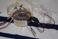
The secondary wires were cut, the laquer scraped off with a knife (followed by an emory cloth polish), and the old secondary output wires were soldered on. Then the windings were secured with tape and the plastic film was wound back on.
The whole process took me about 90 minutes including photography. With the transformer completely assembled, the output voltage on the secondary was 5.2 V for 120 V input.
Pictures from the various stages of the process below.
~Tom
I figured I'd share... Transformers are not exactly rocket science, but some people seem to be a little intimidated by them.
I have an Antek 2T350 that I intend to use for a project involving 5AR4 rectifiers. These rectifiers have a 5 V filament. The trafo provides 6.3 V. What to do...
Option #1: Insert a 0.68 ohm resistor in series with the 5AR4 filament. This drops 1.3 V across the resistor and voila, 5.0 V across the filament. However, it also dissipates about 2.5 W in the resistor which will need to be gotten rid of.
Option #2: Unwind the secondary a little bit to change the turns ratio from 120:6.3 to 120:5.
I opted for the latter on this project. I counted 21 turns on the secondary. So a little back of the envelope math:
6.3/21 = 0.3 V per turn
5/0.3 = 16.7 turns
So to get a 5.0 V winding, I'd have to make a 16.7 turn secondary. 17 turns aught to be close enough... So if I remove four turns from the existing secondary, the voltage should drop to 5 V (maybe slightly higher). So I set out to remove four turns...
It's quite straight forward. The tape end of the plastic film wrapped around the transformer is found and the tape is removed. Then the plastic film is carefully unwound enough to expose the secondary connections. Taking care not to nick the windings, an exacto/utility knife is used to cut back the adhesive tape wrapped around the core. Note how the ends of the two secondary windings are interleaved between a piece of card stock to ensure that they don't short out. Pay attention to the sequence of the wires. I removed two turns from each end of each winding. The turns are actually bunched up slightly at the termination point, so I could do this and still have the secondary evenly spaced across the circumference of the core. With the now 17-turn secondary, I measured the secondary voltage. I loaded the secondary with a 5AR4 rectifier for this measurement. At 115 V input, I measured 5.0 V. At 120 V, I measured 5.25 V. That's within the +/-10 % normally required for heater windings, so I decided to stop here.
The secondary wires were cut, the laquer scraped off with a knife (followed by an emory cloth polish), and the old secondary output wires were soldered on. Then the windings were secured with tape and the plastic film was wound back on.
The whole process took me about 90 minutes including photography. With the transformer completely assembled, the output voltage on the secondary was 5.2 V for 120 V input.
Pictures from the various stages of the process below.
~Tom
Attachments
Yes, very nicely done. The photos are excellent too. The only pity is that Antek doesn't make it easy to specify either 6.3 & 6.3 or 6.3 & 5.0 at the time of order. The end user shouldn't have to make this modification at all if the factory would just sell him what he needed.
I have been using a slightly different and easier technique. Since I wasn't sure that the two 6.3 volt windings could reliably handle 300 to 500 volts between them, I decided to add another winding. In normal use the rectifier winding operates at the B+ voltage and the 6.3 volt filament winding operates at or near ground potential. The two wires are in close proximity and are touching each other in some Anteks.
I use two ways to add a 5 volt winding. The ugly method, and the pretty method. Since toroids are already rather ugly, the ugly method is my first choice because it is easy. How? Simply take a length of hookup wire that is rated for 600 volts and wind it through the core and hook it up to your rectifier tube. Neatness does not count, or matter. The only critical factor is the number of turns. How many do you need? That depends on the transformer. Some need as few as 11 and some need up to 20. How do you know? Wind 15 or so turns and measure the voltage. Add or subtract as needed. I start with a long piece of wire (about 20 feet) loop half of it through the core and wind from both ends. At 10 turns or so, connect a rectifier tube (or suitable load) across the ends, Tape up the HV winding so you dont fry yourself, and make a measurement. Heep adding turns until you are just over 5 volts. The voltage will drop slightly when all the secondaries are hooked up.
The pretty method. Use the ugly method to find the number of turns needed. Wind the new secondary with #18 or 20 enameled wire right on top of the existing tape cover. Solder hookup wires to the ends and apply heat shrink. Make a new cover by wrapping Kapton tape on top of the new winding.
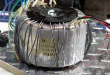
The picture shows an Antek 4T360 with two added 5 volt windings. The Antek powers 2 Simple P-P boards, each wired for mono PPP and I am cranking the EL84's at 435 volts! Result...50 WPC!
I use two ways to add a 5 volt winding. The ugly method, and the pretty method. Since toroids are already rather ugly, the ugly method is my first choice because it is easy. How? Simply take a length of hookup wire that is rated for 600 volts and wind it through the core and hook it up to your rectifier tube. Neatness does not count, or matter. The only critical factor is the number of turns. How many do you need? That depends on the transformer. Some need as few as 11 and some need up to 20. How do you know? Wind 15 or so turns and measure the voltage. Add or subtract as needed. I start with a long piece of wire (about 20 feet) loop half of it through the core and wind from both ends. At 10 turns or so, connect a rectifier tube (or suitable load) across the ends, Tape up the HV winding so you dont fry yourself, and make a measurement. Heep adding turns until you are just over 5 volts. The voltage will drop slightly when all the secondaries are hooked up.
The pretty method. Use the ugly method to find the number of turns needed. Wind the new secondary with #18 or 20 enameled wire right on top of the existing tape cover. Solder hookup wires to the ends and apply heat shrink. Make a new cover by wrapping Kapton tape on top of the new winding.
The picture shows an Antek 4T360 with two added 5 volt windings. The Antek powers 2 Simple P-P boards, each wired for mono PPP and I am cranking the EL84's at 435 volts! Result...50 WPC!
Attachments
I've been winding my own "custom" EI transformers years, using cores salvaged from discarded solid-state gear. Most of these were used in power supplies for reproduction vintage amateur radio gear.
I got my introduction to toroid-o-rama when I started building an Elecraft K2 with the internal antenna tuner. I thought I'd never finish winding them all. By the time it was done I had to buy some "Preparation T" to soothe the itching and burning of my inflamed toroidal tissues!
The one thing I did take away from all that was that when winding toroids, one pass through the core counts as one turn.
Seriously, this is really excellent stuff, fellows. I've been considering using toroidal transformers in the power supply of my next build, and I'll have to keep these methods in mind...
Folks,
I figured I'd share... Transformers are not exactly rocket science, but some people seem to be a little intimidated by them.
I have an Antek 2T350 that I intend to use for a project involving 5AR4 rectifiers. These rectifiers have a 5 V filament. The trafo provides 6.3 V. What to do...
Option #1: Insert a 0.68 ohm resistor in series with the 5AR4 filament. This drops 1.3 V across the resistor and voila, 5.0 V across the filament. However, it also dissipates about 2.5 W in the resistor which will need to be gotten rid of.
Option #2: Unwind the secondary a little bit to change the turns ratio from 120:6.3 to 120:5.
I opted for the latter on this project. I counted 21 turns on the secondary. So a little back of the envelope math:
6.3/21 = 0.3 V per turn
5/0.3 = 16.7 turns
So to get a 5.0 V winding, I'd have to make a 16.7 turn secondary. 17 turns aught to be close enough... So if I remove four turns from the existing secondary, the voltage should drop to 5 V (maybe slightly higher). So I set out to remove four turns...
<snip>
~Tom
Hello,
If this was Diyrocket.com we would be discussing the ratio of sulfur to powered zinc not transformer turn ratios. If I had 100 million dollars to build a stem cell lab I would be sorting gram negative bacteria with a laser.
Transformers are about impedance matching for a given load. Adjusting the resistor for option #1 or the number of turns for option number 2 is more trial and error than back of the envelope calculation.
0.68 ohms was more of a street trap than a real number.
I am going to start my trial and error with 2 five watt 0.5R wire wound resistors in series.
DT
All just for fun!
Hello,
Transformers are about impedance matching for a given load. Adjusting the resistor for option #1 or the number of turns for option number 2 is more trial and error than back of the envelope calculation.
0.68 ohms was more of a street trap than a real number.
I am going to start my trial and error with 2 five watt 0.5R wire wound resistors in series.
I'm not sure what your point is. I arrived at the 0.68 ohm by back of envelope calculation. The 5AR4 draws 1.9 A at 5.0 V.
(6.3-5)/1.9 = 0.684 ohm
0.68 is the closest standard value. Done. No trial and error. I hooked it up and got 5.0 V across the rectifier filament.
~Tom
I have been using a slightly different and easier technique. Since I wasn't sure that the two 6.3 volt windings could reliably handle 300 to 500 volts between them, I decided to add another winding. In normal use the rectifier winding operates at the B+ voltage and the 6.3 volt filament winding operates at or near ground potential. The two wires are in close proximity and are touching each other in some Anteks.
That's actually a really good point. The two 6.3 V windings look like they're wound as a pair. I.e. as two parallel strands of wire. They are touching most of the way, though, they are insulated by enamel.
It my case, it's OK as each winding will feed a separate rectifier so they'll both be at 400 V potential. Hence, the differential potential will be close to zero. I'll use a separate transformer for my 6.3 V and 5.0 V DC filament supplies. That was my original thought anyway. I'm thinking now to just add a pair of windings. Hmmm...
As far as the wire gauge, I'd probably go with a 3 A/mm^2 current density. That what I was taught in switchmode class in college anyway.
~Tom
Great photos and write-up Tom. There is one other method too, just for info, I haven't tried it but it sounds feasible, wind some windings "backwards" on the outside of the tranny from the 6.3V taps to act as a bucking winding, about 4 turns by the sounds of it, to get the 6.3V back to 5V. It is a good thing though that a DIY'er can undo the tape, wind whatever he wants onto those trannies, tape it all back up, and it all looks stock standard. Or just lay the windings on the outside. All good!
Ok, using ohms law either in ones head or a calculator available on line it is simple to come up with a resistor sized to drop the voltage to the desired 5.0 volts. When you start winding wire around a toridal transformer I start to wonder what ga wire to use and if the added winding is going to be able to supply the needed 1.9 A the 5Ar4 is going to draw. Is 18-20 ga big enough? What is the calculation to come up with the ga of wire?
Thanks for sharing. I did something like that here. http://www.diyaudio.com/forums/tubelab/148378-tubelab-se-alternate-power-transformer-2.htmlThese rectifiers have a 5 V filament. The trafo provides 6.3 V. What to do...
According to the seller the core is pretty robust, a bit over spec., so minor changes aren't too likely to be a problem unless you are pushing their limits anyway.
I tried the added winding technique, but the problem I ran into is that they no longer fit into the nice cover I have for them (from Antek) so no longer can be mounted on the outside of the chassis, if I want permission to place my amp in a visible location...
I tried the added winding technique, but the problem I ran into is that they no longer fit into the nice cover I have for them (from Antek) so no longer can be mounted on the outside of the chassis, if I want permission to place my amp in a visible location...
I'm not sure what your point is. I arrived at the 0.68 ohm by back of envelope calculation. The 5AR4 draws 1.9 A at 5.0 V.
(6.3-5)/1.9 = 0.684 ohm
0.68 is the closest standard value. Done. No trial and error. I hooked it up and got 5.0 V across the rectifier filament.
~Tom
Hello,
The short version is: I am skeptical. I don’t think that it is that simple.
http://www.antekinc.com/pdf/AN-2T350.pdf
Assume that the 3 other secondary windings are connected to loads and we are considering the remaining 6.3 volt secondary. The output is rated at 6.3 volts, 4 amps with 115 volts input. Now increase the input voltage to a more typical 120 + value the output voltage will go up by 5% or so. Next change the load to 2 amps for a 5Y3 or 1.9 amps for a 5AR4. Considering the internal impedance (regulation) of the transformer my best estimate is that there is closer to 2.2 volts to burn across a resistor rather than 1.3 volts assumed.
I can see the adjustments to the value of R in option number 1 or the number of turns removed for option number 2 being done empirically (under test, one turn at a time).
DT
All just for fun!
I'm not sure what your point is. I arrived at the 0.68 ohm by back of envelope calculation. The 5AR4 draws 1.9 A at 5.0 V.......The short version is: I am skeptical. I don’t think that it is that simple.
Mr. OHM hasn't been proved wrong yet, and it IS that simple IF your 6.3 volt winding actually produces 6.3 Volts with the entire transformer operating under the same load it will see in the amp, AND your 5AR4 actually draws 1.9 amps. Now the two conditions listed above are rarely true, but the calculation is a good place to start, and probably closer than what you would get off of the 5 volt winding of a Hammond transformer.
According to the seller the core is pretty robust, a bit over spec., so minor changes aren't too likely to be a problem unless you are pushing their limits anyway.
It is usually a good idea to have some reserve capacity and an added rectifier winding will eat about 10 VA of capacity. My experiences show that even a 1T200 doesn't get too hot when running at 125 VA. The 4T360 that I am using could easilly power two of these amps, so it doesn't break a sweat.
I start to wonder what ga wire to use and if the added winding is going to be able to supply the needed 1.9 A the 5AR4 is going to draw. Is 18-20 ga big enough? What is the calculation to come up with the ga of wire?
I have seen dozens of charts and calculations to arrive at the needed wire size. They vary over a 10 to 1 range! Look at this one:
American Wire Gauge table and AWG Electrical Current Load Limits with skin depth frequencies
Note that a #20 can handle 1.5 amps for "power transmission" and 11 amps for "chassis wiring". A 10 foot piece of #20 wire has about 0.1 ohm. It will dissipate about 200 milliwatts at 2 amps and barely gets warm. I use # 18 and it doesn't get warm at all.
I've been winding my own "custom" EI transformers years, using cores salvaged from discarded solid-state gear.
Back in high school electronics class we learned all about vacuum tubes. There were a few chapters in the books about solid state stuff, but no reall applications since it was a public school running on donated junk for labs. I wanted to play with some of the new fangled solid state stuff, but power transformers were not available. You could not buy a 50 VCT 4 amp transformer in any of the usual catalogs in 1968. Digikey and Mouser did not exist yet. We had Allied (still around) Lafayette, and Radio Shack. So, you take apart the power transformer from an old TV set. Remove all windings except the primary and wind your own secondary. I used ordinary masking tape for insulation between the layers and the transformers lived. In fact I recently found an amp that I made in 1970 and the transformer was still working. I use Kapton tape today.
According to the seller the core is pretty robust, a bit over spec., so minor changes aren't too likely to be a problem unless you are pushing their limits anyway.
My current draws will be:
350 V: 180 mA --> 63 VA
5.0 V: 3.8 A --> 19 VA
12 V: 2.2 A --> 26.4 VA
TOTAL: 108 VA.
That's assuming I succeed in adding a 12 V winding for my switching regulators for the filaments. I also need the transformer to fit in the Antek steel cover...
If the primary can generate enough flux and the core has enough cross sectional area to transfer 200 VA, it should easily be capable of handling the 108 VA I'm throwing at it.
I'll be using two 12 V windings. Each will have a current draw of about 1.1 A. Designing for 1.5 A with 3 A/mm^2 current density yields 0.5 mm^2 cross sectional area of the wire. Recall that A = pi*r^2, hence the radius of the wire should be 0.4 mm. I.e. the diameter of the wire be 0.8 mm. According to Wikipedia, the corresponding wire size is AWG 20 (0.812 mm diameter).
The 3 A/mm^2 current density was mentioned as a rule of thumb by my instructor in a switchmode class I took in college. The instructor had spent a fair amount of his life designing power supplies - including winding transformers for use in switchmode power supplies. 3 A/mm^2 was a reasonable compromise between wire gauge and ohmic losses (temperature increase).
~Tom
The 3 A/mm^2 current density was mentioned as a rule of thumb by my instructor in a switchmode class
The wire losses are slightly higher in a switchmode transformer than in a conventional transformer since the conventional transformer runs at 50 or 60 Hz and a switchmode transformer runs somewhere between 20 KHz and 2 MHz. The skin effect will reduce the effective cross section area of the wire as the frequency increases.
I have used a #20 wire at 1.9 amps before, so it should be cool at 1.1 A.
Hello,Mr. OHM hasn't been proved wrong yet, and it IS that simple IF your 6.3 volt winding actually produces 6.3 Volts with the entire transformer operating under the same load it will see in the amp, AND your 5AR4 actually draws 1.9 amps. Now the two conditions listed above are rarely true, but the calculation is a good place to start, and probably closer than what you would get off of the 5 volt winding of a Hammond transformer.
Kirchhoff's second law remains in force as well. Every time I have done that back of envelope calculation for a heater voltage dropping resistor I have ended up chasing the value.
Mr. ohm needs to plug in the total impedance; the heater, the added voltage dropping resistor and the transformer internal impedance. From your approach whack it with a bigger hammer then back off a little.
Or to look at it from the other side it is easier to remove transformer windings than put them back in.
My original point is the same as yours, that 0.68R value will require some adjustment on the bench.
DT
All just for fun!
Or to look at it from the other side it is easier to remove transformer windings than put them back in.
My wood shop teacher keeps telling me that it is far easier to remove wood than to put it back, yet I keep screwing up!
- Home
- Amplifiers
- Tubes / Valves
- Turning a 6.3 V secondary into a 5 V secondary on an Antek 2T350