It is. He will need a negative supply not to mention the CCS needed for best balance. And after all that work there's no guarantee it will sound better. This is not a personal opinion.
Or he can use a common cathode stage direct coupled to a cathodyne. No negative supply, low parts count, excellent balance of AC, balanced source impedance, more available gain for feedback, and relatively insensitive to tube aging/variation.
I just don’t know that much about the working of tubes to know how crazy I sound.
Martian Logan – Aeon – Electrostatic Speaker
DIY Sub – Martian Logan Drivers and Rythmik 600w non servo amp
Your knowledge of tubes doesn't sound all that crazy to me. But someone may commit you to a straitjacket for believing you have Martian speakers.
..Todd
Last edited:
Sorry, I've been away for a few days.
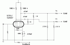
If you want to balance up the phase splitter then, assuming the current resistor values are reasonably accurate, it is the lower 270K which needs to be increased. You are not adjusting a circuit which is already nominally balanced (which could need trimming on either side) but creating balance in a circuit which is currently unbalanced because the phase splitter triode has insufficient gain - you need infinite gain to get balanced output from identical resistors! The 47K resistor to ground adds further loading, so reduces the loop gain seen by the 'error signal' generated at the junction of the 270K resistors. You can't increase the 47K by much, as this also provides grid bias for the output. Some versions of this circuit separate the feedback and grid bias functions into separate resistors - more components, but potentially better balance.
Unlike other phase splitters, this one simply inserts an extra stage into one phase; this extra stage should have a gain of exactly -1. Negative feedback is not magic. To get -1 you either need an op-amp instead of a triode, or to modify the resistors.
Of course, a separate question is "how much balance do you need?" Lack of balance means that the second-order distortion in the output stage is not fully cancelled - some might like this as it would add a little SE flavour.
- some might like this as it would add a little SE flavour.
Oh, a PP amplifier sounding like SE but with better bass... Wait, that can't be a bad idea.
If you feel like modding the circuit you might want to try the following schematic:
Attachments
Hello All!
I wonder if anyone knows what happen to Cassiel? I was chatting with him several years ago about the splitter above- topology and exact values are taken from Leben amplfier, but I do not know the HT voltage. In original design it is probably abput 200V. Can anybody help me with this ? Thank You
I wonder if anyone knows what happen to Cassiel? I was chatting with him several years ago about the splitter above- topology and exact values are taken from Leben amplfier, but I do not know the HT voltage. In original design it is probably abput 200V. Can anybody help me with this ? Thank You
- Status
- This old topic is closed. If you want to reopen this topic, contact a moderator using the "Report Post" button.
