I have chosen to build a monoblock version of the baby huey amplifier design for my first build. For those of you who have done this before, I have a few questions.
First off, could I use a 5Y3GT rectifier tube instead of the solid state rectifier shown in the diagram? Additionally, what is the CCS subcircuit, and what role does it play? I am confused about what the function of the LED is, and why the schematic shows two wires going the other channel's CCS. Since I am building a mono amp, what becomes to those two wires? Additionally, since I am building a mono amp should I change the pair of resistors on the leads going to HT left and right to a single resistor equivalent to the parallel set? If you have any input I would really appreciate it.
Thanks,
-Matt
An externally hosted image should be here but it was not working when we last tested it.
First off, could I use a 5Y3GT rectifier tube instead of the solid state rectifier shown in the diagram? Additionally, what is the CCS subcircuit, and what role does it play? I am confused about what the function of the LED is, and why the schematic shows two wires going the other channel's CCS. Since I am building a mono amp, what becomes to those two wires? Additionally, since I am building a mono amp should I change the pair of resistors on the leads going to HT left and right to a single resistor equivalent to the parallel set? If you have any input I would really appreciate it.
Thanks,
-Matt
re 5y3gt, yes i dont see why not as long as you obey it's max cap ratings etc. You will need to use the 5v winding on you power tx, so will have to think how you will get the -15v for the CCS.
The CCS is a morgan jones design (see book 'valve amplifiers') the led provides a Vref, take the VBE of the lower bc547b (0.7v) from the 1.7V led ref to give the voltage through the 1k. 1v / 1kr = 1ma CCS for the phase splitter. two wires go as you need a -15v supply, and the ground.
just use the single 47R, you may need to tweak for the final desired B+. If you are using a valve rectifier you will probably need choke, do a CLCRC supply, tweaking for the first C for setting B+. use the duncan amp tools PSU simulator to help.
so will have to think how you will get the -15v for the CCS
If you're using the Freed transformer I think I saw a spare 6.3v (0.9A) tap that could be used to provide your negative supply, will give about -17v but thats ok ( see post 5 of Baby Huey thread )
If you're using the Freed transformer I think I saw a spare 6.3v (0.9A) tap that could be used to provide your negative supply, will give about -17v but thats ok ( see post 5 of Baby Huey thread )
Yes, I am using that Freed transformer, thanks for the info.

Another question, my power transformer is rated at 750 volts center tapped, in order to get the voltage closer to the 350 range, I was planning on wiring the rectifier between the center tap and one outer tap to get half the voltage. Will this work for the Baby Huey design, or am I looking at it the wrong way?
you are looking at it the wrong way. 750V CT is 375V per side of the centre tap, each operating on opposite phases - in effect two 375V OPTs operating side by side. Just follow the diagram sir. And download Duncan Amps PSUDII and get used to using it! It saves heaps of time and answers a lot of questions.
Another question, my power transformer is rated at 750 volts center tapped, in order to get the voltage closer to the 350 range, I was planning on wiring the rectifier between the center tap and one outer tap to get half the voltage. Will this work for the Baby Huey design, or am I looking at it the wrong way?
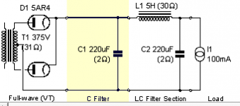
You want a full wave center tap, see pic:
Note: Disregard the component values, the FWCT config is what is relevant.
Attachments
You want a full wave center tap, see pic:
Note: Disregard the component values, the FWCT config is what is relevant.
Ok, I got the power supply design software, and I have what I believe is a working arrangement. It puts out 350 volts and draws .33A plate current once the transients die out. Take a look at this arrangement and let me know if you see any flaws.
An externally hosted image should be here but it was not working when we last tested it.
thats a LOT of capacitance for a RCLCRC network... and the first cap may be over-large for the rectifier too - what is the peak current across the 5Y3 at start-up?
The peak current is 1.06A, the max transient current for the tube is 5.5A per plate. I just arrived at those capacitor values from trying to reduce the ripple in the plot, what do you think would be more reasonable capacitor values.
Thanks for the info
-Matt
Hi Matt,
350v is at the top of the design range, why not try first for 320v and then sort out the ripple afterwards. Play about with the first cap, this can have a big effect on the final B+.
Ps caps can get a lot more expensive above 350v working voltage.
Ok, here's what I have now, it runs at 320V and still about .33A. The peak transient current is .883A. Current dies to steady state value in about a second. Do these capacitor values look more conventional?
An externally hosted image should be here but it was not working when we last tested it.
yeah that looks more like it! What are your ripple figures?
I'm not sure what the traditional way to quote ripple is, but here is the steady state HV signal:
V(t) = 320.9175 + .009sin(748t)
The units of the function are volts, and the angular frequency is in radians per second. What that boils down to is a ripple with 9 millivolt amplitude and 120hz frequency. Are these figures good, or bad?
9 millivolts should be just fine! If you take a look at PSUDII, you can deduce ripple fairly quickly - take a sample around 5 seconds in and look for the min and max figures...
Some here would like to present the ripple in db. Meh, if you like that sort of thing, fine, and obviously appropriate if ytou are discussing ripple noise, or rejection levels in a topology.
Me, I understand volts and the ratio of a small voltage to the overall voltage. KISS I say.
Some here would like to present the ripple in db. Meh, if you like that sort of thing, fine, and obviously appropriate if ytou are discussing ripple noise, or rejection levels in a topology.
Me, I understand volts and the ratio of a small voltage to the overall voltage. KISS I say.
- Status
- This old topic is closed. If you want to reopen this topic, contact a moderator using the "Report Post" button.
- Home
- Amplifiers
- Tubes / Valves
- First time baby Huey amplifier build