Now I am still im my infancy with regard to tubes. So I apologize to anyone offended by my stupid questions here.
I found a 0D3 regulator tube or so I am told. I was wondering if I can use it in a preamp that I plan to use. I need about 144-150 or so volts on the plate of a 5687 tube for this project. My power supply is going to be a 300-0-300 transformer followed by a 30H 40ma choke, a 50mfd/500 cap, a 30H choke, and a 50mfd cap. I'm going to guess that I will be somewhere around 220 volts B+ here. I will need to drop off the excess voltage so I will need to figure a resistor. The tube I am assuming will draw about 12MA. per section?
Now, can I use the 0D3 in place of the voltage dropping resistor to end up with my 150volts? I am told it will give 150volts out. If so how do I wire it up? Or am I trying to do something very stupid here?
Frank? anyone?
Thanks
Joe
What you have to do is put a bias resistor from B+ to the plate of the tube and then wire the cathode to ground. The resistor will drop the B+ voltage difference from what the OD3 drops. I'm not sure what B+ you are using, but you have to decide on what resistor to use to drop the voltage at an acceptable rate without dissipating too much heat. Also, put a small cap accross the OD3 from plate to cathode, this will minimise the terrible noise some OD3's make.
This tube works exactly like a zener diode and all you need is a resistor to use it in the amp, the cap is an option and will improve the noise floor of the amp.
Hope this helps. If you need better ideas, I can draw you a diagram give you examples of what resistor to use.
This tube works exactly like a zener diode and all you need is a resistor to use it in the amp, the cap is an option and will improve the noise floor of the amp.
Hope this helps. If you need better ideas, I can draw you a diagram give you examples of what resistor to use.
Hi,
The OD3 is a mercury vapor cold cathode voltage regulator suitable for 150VDC at 40mA max.
It needs a striking voltage ( igniting it) of 185V min. so, yes this should work.
You'll need to calculate a dropper resistor to arrive at the "striking" voltage ( a little higher won't hurt but too low and the tube won't light up) using Ohms' law.
It is also recommended to decouple the tube using a 0.100uF filmcap (max) to prevent the tube from oscillating.
Just like a zener it will try to clamp the output at 150V.
OD3
Check the eye icon for pinout, "stabiliser" for technical data.
A more recent variant but much lower current is the OA2.
I have no hands on experience with the OD3 but noticed David Manley uses some in a preamp...
Cheers,")
Now, can I use the 0D3 in place of the voltage dropping resistor to end up with my 150volts? I am told it will give 150volts out.
The OD3 is a mercury vapor cold cathode voltage regulator suitable for 150VDC at 40mA max.
It needs a striking voltage ( igniting it) of 185V min. so, yes this should work.
You'll need to calculate a dropper resistor to arrive at the "striking" voltage ( a little higher won't hurt but too low and the tube won't light up) using Ohms' law.
It is also recommended to decouple the tube using a 0.100uF filmcap (max) to prevent the tube from oscillating.
Just like a zener it will try to clamp the output at 150V.
OD3
Check the eye icon for pinout, "stabiliser" for technical data.
A more recent variant but much lower current is the OA2.
I have no hands on experience with the OD3 but noticed David Manley uses some in a preamp...
Cheers,
Hi,
I don't know what you need, this kind of tube only consist of an anode, a cathode and gas.
From the link posted you can easily figure it out:
From browser menu, edit, find on this page: 4AJ.
Nope...does anyone? I worked closely with the importer... never saw a single schematic form Manley other than those published in a little book he once published and that's years ago anyway.
It doesn't cost an arm and a legg to try out so why not give it a go and see what you like best?
Cheers,
I can't seem to find any other data.
I don't know what you need, this kind of tube only consist of an anode, a cathode and gas.
From the link posted you can easily figure it out:
From browser menu, edit, find on this page: 4AJ.
Do you happen to have any schematics from David Manley?
Nope...does anyone? I worked closely with the importer... never saw a single schematic form Manley other than those published in a little book he once published and that's years ago anyway.
In your opinion is this a good idea or one that I should drop?
It doesn't cost an arm and a legg to try out so why not give it a go and see what you like best?
Cheers,
I believe the OD3 is actually a Krypton tube, not Mercury Vapour.
At the moment, I have nothing on this computer to use for drawing a schematic of the OD3 setup. However, for calculating the resistor, find out the idle current of the tube and calculate for a resistor that maintains just above whatever output current you intend to use for the specified voltage drop. You will need a power resistor here since over 100V at 15 - 40 mA will give in the vicinity of 2 - 4W of dissipation.
As soon as I get to a computer that has what I need to make the diagram, I'll draw it for you.
Hi,
I think you're absolutely correct.
My source stated mercury vapour which made me frown...
We have the following gasses in this type of cold cathode tubes:
Neon, Argon, Krypton and possibly a combination of them, although I somehow doubt the latter.
The OD3 hasn't seen much use in audio circuits throughout the history but has been used in scopes and regulated benchsupplies...
Indicating only 9 and this is just an educated guess) that it was considered too expensive by engineers to use in what they quite likely considered to be "inferior" audio circuits.
Nowadays, gasregs are relatively cheap and have every potential to lift an ordinary circuit to exceptional levels...and they're much less noisy than most zeners.
Guess you know where I stand on this by now?
I believe the OD3 is actually a Krypton tube, not Mercury Vapour.
I think you're absolutely correct.
My source stated mercury vapour which made me frown...
We have the following gasses in this type of cold cathode tubes:
Neon, Argon, Krypton and possibly a combination of them, although I somehow doubt the latter.
The OD3 hasn't seen much use in audio circuits throughout the history but has been used in scopes and regulated benchsupplies...
Indicating only 9 and this is just an educated guess) that it was considered too expensive by engineers to use in what they quite likely considered to be "inferior" audio circuits.
Nowadays, gasregs are relatively cheap and have every potential to lift an ordinary circuit to exceptional levels...and they're much less noisy than most zeners.
Guess you know where I stand on this by now?
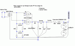
Thanks for the help here. A schematic would be helpful since I am not functioning too good today. Its amazing that taking a few days off can seem like more work than actually going to the job. I had a nice day planned in the garage only to have my plans restructured by the wife. She got her work done, mine is still setting there unfinished.
Frank
I figured what pin 5(anode) is and pin2(kathode) pins 3 and 7 are marked J. What is J?
Sorry, its been a long long day.
Joe
Frank
I figured what pin 5(anode) is and pin2(kathode) pins 3 and 7 are marked J. What is J?
Sorry, its been a long long day.
Joe
Hi,
Why does that sound so familiar?
I was wondering about that too...don't take my word for it but I think it means " internally connected".
If this is so, you'd better leave those alone.
I'll see if I can find the appropiate info in one of my databooks for you...so hang in there.
Oh, I see I have meetings scheduled for tomorrow, in fact for most of the week...maybe someone could be so kind to look this up for Joe?
Cheers,
She got her work done, mine is still setting there unfinished.
Why does that sound so familiar?
I figured what pin 5(anode) is and pin2(kathode) pins 3 and 7 are marked J. What is J?
I was wondering about that too...don't take my word for it but I think it means " internally connected".
If this is so, you'd better leave those alone.
I'll see if I can find the appropiate info in one of my databooks for you...so hang in there.
Oh, I see I have meetings scheduled for tomorrow, in fact for most of the week...maybe someone could be so kind to look this up for Joe?
Cheers,
IIRC, theres two pins that are joined in the 0D3, so that if the tube is missing from the socket, you can use it as a fuse, kind of..
0D3 is 40mA max, 150v ±5v regulation.
it needs at least 5ma flowing through it though, to stay lit.
so, say you have 300v b+, you need a resistor from B+ to the anode of the 0D3 for 150v 40ma =3,75K.
now, at the anode of the 0D3 you can pull 0...35ma, and it will stay regulated at 150±5v. if you pull more than 35mA the 0D3 will extinguish though (it will no longer have at least 5mA flowing through it) and you will lose regulation.
You're all wrong.
take the total load and add half the VR tube's current max to it. So, if we are regulating a stage with a 12AU7 in it, we add 20mA plus 10mA... 30mA total current. Then we take the total voltage BEFORE the VR tube stage. Let's say 200v. So, we need to regulate 50v, at 30mA load... this means we need a resistor of 1660 ohms, 2 watts.
I just built an amp with all VR tubes in the PSU. Trust me.
Looks to me like Joel is right here.
I have built and worked on many circuits with regulator tubes in them, I've grown to like the OD3 a lot. I also design many of my circuits with OD3's since I have a whole box of them.
The "J" means jumper, this is so that you may wire the circuit not to work if the OD3 is removed. The reason this tube was designed this way is because the dropper resistor will give the load the full B+ voltage since the OD3 isn't there to drop it. Basically, you could wire the output of the OD3 circuit through the jumper before it gets to the load circuit, this way, if you pull the OD3, the load is cut off instead of given full B+.
Sorry but I still can't get a diagram. I'll try tomorrow at flight school, they have a computer with some software on it...
Joel said:You're all wrong.
Well, I could go into excruciating detail but I'm too damn tired so pffbt.
Tim
Joel
If I understand you correctly you are figuring half the current of the 0D3 and that is 20ma, and adding 10ma which is the current draw of one section of a 12AU7. This yealds a total of 30ma. With a given B+ of 200 volts we need to drop 50 volts so we need a resistor before the 0D3 of 1.666 @ 1.5 watts or probably better to double the wattage rating to be safe.
So if I were to use 2 sections of a 5687 that are roughly 12ma ea and a supply voltage of say 225 volts I would figure a load of half the VR
plus 24ma or 44ma dropping 75volts, a resistor of 1.7k at 3.3 watts.
So in other words two sections of a 12AU7 at 10.5ma.ea would work and two sections of a 5687 at 12ma each would max out the regulator? Or is my thinking wrong here?
Joe
You are exactly correct up until that last paragraph which I don't quite understand. You can use the VR tube with any load you like - there is no "maxing it out", provided you put enough resistance in front of it to drop the excess voltage.
The reason we choose a value of half the VR tube's max current is so that it is allowed to swing up and down without maxing out or cutting off as the current demand in the amp goes up and down - in other words, we are putting it in the middle of its curve.
Things to keep in mind though are that the best regulation will occur when you have a very low current demand with a very large dropping resistor in front of the VR tube. Why? Well, think of it as having a much greater "impact" on the voltage drop with only a small change in the VR tube's current. If you have a very small dropping resistor, the VR tube has to work very hard (big current swing) in order to drop the same amount of voltage.
Hi,
partnumber - base type
0D3 Octal
VR150
VT-139
nominal voltage - regulation voltage
150 4
ignition voltage - current range (mA)
160 5 - 40
Current (mA) Voltage (V)
5.0 147.6
7.5 147.7
10.0 147.7
12.5 147.8
15.0 147.9
17.5 148.3
20.0 148.7
25.0 149.7
30.0 150.9
35.0 152.0
40.0 153.0
Measurements may vary a little but this is fairly typical for a OD3.
Hope that helps,
- Home
- Amplifiers
- Tubes / Valves
- How do you use a 0D3 regulator?