The "Tree Streets" so named after trees are part of the old town and a historical district. As such they are limited to yard sales once a year, and most houses have a sale on that day. I don't get the paper so I wasn't aware it was today until I drove by around 2pm and saw a sign. I called the wife and said "lets go".
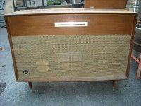
I missed a Sears Console Stereo for $40, but found this for $30.
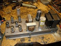
Webcor 801068-16. Probably 8WPC. 12BA5s in pp with rather small opts. Active tone controls on a separate PCB.
Nice that the all important schematic is included. Interesting of note is the separate feedback winding in the OPTs.
Too bad it does not have an FM stereo tuner in it.
It will need new caps before powering it up, but it looks like it has been kept high and dry although quite dusty inside.
I missed a Sears Console Stereo for $40, but found this for $30.
Webcor 801068-16. Probably 8WPC. 12BA5s in pp with rather small opts. Active tone controls on a separate PCB.
Nice that the all important schematic is included. Interesting of note is the separate feedback winding in the OPTs.
Too bad it does not have an FM stereo tuner in it.
It will need new caps before powering it up, but it looks like it has been kept high and dry although quite dusty inside.
Attachments
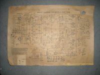
The schematic does not seem to be complete. Or they did a basic system and added options.
There is a quarter wave dipole FM antenna on the back, and it leads to a balumn in the patch pannel in the lower left corner.
But, there is no indications in the schematic of an FM tuner.
The phono input seems to be ceramic without RIAA equalization.
Nine tubes in the schematic, nine tubes in the two chassis but no indication on the schematic where the two chassis are partitioned.
Furthermore, The schematic shows the phase splitters as V2B and B6 B which makes no sense as there are only five tubes on the amp chassis.
Looks like a challenge to get it going again.
Consoles are how I got into this whole gig
Yeah, thats how I started too, but the rest of the story was a bit different. I was about 12 years old and my parents bought one of those new fangled stereo consoles. I inherited the old Magnavox HiFi (P-P 6V6's). I simply removed the phono cartridge and twisted the wires to a guitar cable and plugged in. It worked, but wasn't very loud. One of the older kids in the neighborhood was a ham radio guy. He told me that I needed a preamp. He showed me how to make one with old radio parts and I was hooked. That was 45 years ago.
Back then all the tubes, transformers and other parts you needed were as close as the local trash dump. I was making guitar amps out of TV sets by the time I was 15. It seems that not too long ago tube TV's, radios, and console stereos were occasionally found in the trash. Not anymore.
I used to salvage TVs as well. Free for the taking just walk around the neighborhood on a weekend with a wheelbarrow and load up. I used to repair stereo systems for my friends and fellow classmates in HS.
I must have seen 50 TVs for sale this weekend for $5 ea. All modern plastic behemoths. Most probably didn't' work. I don't understand why people put broken electronics for sale and claim it works.
One group of youngsters at a frat house told me they knew where a gigantic tube TV set was, or they think they knew where one was....
They were all pretty much plastered so I moved on figuring I'd spend my time better checking out the rest of the sales. A block later I got the Webcor.
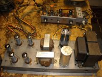
OPTs are the same height and width as Edcor XPP10-8-10Ks but the stack is a bit thinner. 3/4" vs 1" for Edcor.
Since they went through the trouble of winding an additional feedback winding I'm optimistic that they might end up sounding reasonable.
The schematic and additional connectors on the back of the amp chassis leads me to speculate that they had a configurable design in which AM and FM tuners were options.
If so, then the Power Transformer is over-designed for the basic amp and turntable.
I'm fighting the urge to put an incandescent lamp and variac in series with the power cord and flip the switch, then slowly bring up the voltage.
I must have seen 50 TVs for sale this weekend for $5 ea. All modern plastic behemoths. Most probably didn't' work. I don't understand why people put broken electronics for sale and claim it works.
One group of youngsters at a frat house told me they knew where a gigantic tube TV set was, or they think they knew where one was....
They were all pretty much plastered so I moved on figuring I'd spend my time better checking out the rest of the sales. A block later I got the Webcor.
OPTs are the same height and width as Edcor XPP10-8-10Ks but the stack is a bit thinner. 3/4" vs 1" for Edcor.
Since they went through the trouble of winding an additional feedback winding I'm optimistic that they might end up sounding reasonable.
The schematic and additional connectors on the back of the amp chassis leads me to speculate that they had a configurable design in which AM and FM tuners were options.
If so, then the Power Transformer is over-designed for the basic amp and turntable.
I'm fighting the urge to put an incandescent lamp and variac in series with the power cord and flip the switch, then slowly bring up the voltage.
I'm fighting the urge to put an incandescent lamp and variac in series with the power cord and flip the switch, then slowly bring up the voltage.
 go on - I dare ya!
THe PTX is sitting over a through-chassis mounting cut-out, so I suspect either the PTX has been replaced at some time or the different configurations were supplied with different PTX's depending on VA requirements...
Last edited:
Transformer looks original. Still has the mfg tag under one corner.
With the Tone Control / pre-amp removed, and 115VAC in I get 540VAC CT at the 5U4 and 12.9VAC on the heaters. So the transformer looks good. B+ is 291.7 vs 285 on schematic. Not surprising with the tone control / pre-amp removed.
B+ comes up at 292V, all heaters come up. No sound. Powered down and started searching for replacement caps. I'll rework it before applying power again. Needs a fuse, IEC power connector, X2 Cap on power inlet for noise, etc.
Found a Mallory 80uf/450V, 50uF@450V, 30uF@450V cap in my collection. I could wire it with the 30uF section first after the 5U4, and add a 10uF 450V cap in series to get 40uf, then use the 80uF as the second section (Screen supply) and follow it with the 50uF as the phase splitter filter.
25uF at 25V can be replaced with a discrete instead of in the can.
How critical is the input capacitance value? Spec for 5U4GB is 40uF. Can I get by with the 50uF section? Or do I need to drop back to the 30uF with an additional 10uF cap to get 40uF?
I can dispense with the 60uF for the tuner since there is no tuner.
Last edited:
I finally got the partition figured out. I scanned the schematic and printed it on 11" X 17" paper at work. The main chassis has one channel with the voltage amp and phase splitter on the chassis with the output tubes. The other channel has it's voltage amp and phase splitter on the tone control/selector PWB.
I also found that note 6 states that the ac voltages are taken at 1000cycles input , all controls at max ccw except balance, and .....
"A 16 ohm dummy load (or speaker)" .
Bah!
I measured the two 6" speakers and they measured 7 ohm and 9.3 ohm respectively (two different designs). One is a Quam 6A15MT (6" A type 15 ohm chassis mount speaker?). The other is simply marked P1796 and 76P100A.
The tweeters are marked 16P081-2 (16 ohm, 81mm dia? They are close.). They measure 15.1 and 15.6 Ohms.
Since the impedance is greater than the DC resistance, I think it is fair to surmise that this is indeed a 16 ohm system.
I'm not too sure how well it will drive 8 ohm speakers. Probably greater distortion and less power due to the 2:1 impedance shift/missmatch.
So how to proceed from here.
(1) clean up the wiring, add an IEC 3 prong connector, fuse, replace caps, etc and try to get it going with the umbilical chord and tone control/selector assembly.
(2) cut the cord, add an IEC 3 prong connector, fuse, replace caps, etc, add a second tube socket and wire it for the channel missing the voltage amp and phase splitter, and add appropriate connectors to make the main chassis a stand alone amp.
Decisions, decisions.
Why do Guitar amps still use 16 ohm speakers?
I see that Celestion, Jensen and SICA still make 16 ohm speakers. I understand they could be paralleled for 8ohms, or four in parallel for 4 ohms, but Guitar amps traditionally have 4/8/16 ohm taps.
Is there an advantage to a 16 ohm speaker?
My fall-back on this amp is to replace the opts with a set of Edcor XPP10-8-10K transformers I just happen to have in my parts pile.
In that case I'm wondering if the current transformers would make for reasonable guitar amps.
I re-capped it, added a fuse and IEC connector with proper ground, and added a socket for the additional 12AX7 that is needed for the second channel.
I'm going to add terminals for the speakers, input connectors and a dual volume control next, then wire it up and get it going before making any other circuit changes.
I don't like all four output tube cathodes sharing one resistor but I'll leave that for now.
I'm going to add terminals for the speakers, input connectors and a dual volume control next, then wire it up and get it going before making any other circuit changes.
I don't like all four output tube cathodes sharing one resistor but I'll leave that for now.
Attachments
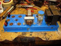
Cleaned up, painted and added terminals.
I still need to add a pot on the input and wire up the gain stage and concertina for one channel, replace the ceramic coupling caps, and add the input RCA connectors.
Then I can find out if it will play.
I still need to add a pot on the input and wire up the gain stage and concertina for one channel, replace the ceramic coupling caps, and add the input RCA connectors.
Then I can find out if it will play.
Attachments
Nice work Steve. Should be nice for you to hear a PP amp for a change! I don't know about the 12AX7 for this duty (from my own expereince), it will work, but I find the 6N1P hard to beat, a tube you are more than familiar with. I guess you just want to hear how it originally sounded, plus with the cathode feedback, should be interesting. Bargains like what you picked up, seem to go for either free or 100 to 200 bucks from what I can see, over here.

Canary yellow laminates and Day-glow orange end caps it is.
Yea, I 'm just curious to hear what it sounds like with the original cathode bias to all four tubes in one 135 ohm resistor. Got to be bad news.
I've got replacement 270 ohm 1W resistors with 330uF low ESR caps ready to replace the original 135 ohm resistor.
Yea, I 'm just curious to hear what it sounds like with the original cathode bias to all four tubes in one 135 ohm resistor. Got to be bad news.
I've got replacement 270 ohm 1W resistors with 330uF low ESR caps ready to replace the original 135 ohm resistor.
- Status
- This old topic is closed. If you want to reopen this topic, contact a moderator using the "Report Post" button.
- Home
- Amplifiers
- Tubes / Valves
- Today was the anual Tree Street Yard Sale event