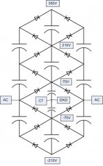
From some previous experiments I still have some transformers from SS amplifiers lying around which I want to use in tube amplifiers. Voltage multiplication comes to mind, and I looked through some threads here at Diyaudio and some Tubecad blogs and eventually built the multiplier as shown in the picture below employing 100uF/450V electrolytics and 1000V/1A diodes. It is a full wave multiplier as shown here.(One could argue that all savings from the transformers went into the electrolytics, but I got these 'surplus' for a very nice price...)
I did some initial testing with a 90V CT transformer and obtained the voltages as shown in the schematic. These voltages are about perfect for an amplifier as the most complex 'baby huey':
- 350V for plates of output tubes (OT) and driver tubes
- 210V for G2 of output tubes
- 70V to the drain of the mosfet source followers that drive the OT
- -70V for bias
- -210V to load the source followers
These are raw voltages, with lots of ripple and will drop under load. To eliminate the ripple I am thinking about source followers as in the 'engineers amplifier' from Pete Millet (P channel mosfets for the negative voltages), but also gyrators or regulators could be used.
Well, to my inexperient eyes it looks doable, but what do you think? I also used 450V capacitors throughout. I am sure that the capacitors between gnd and 70V can be of lower voltage, but I am not really sure about the voltage rating needed for the other capacitors. In the link to the 'full wave multiplier' they write 'Uniform component stress', so maybe all capacitors could be rated for 200VDC (when using a 90V CT transformer)?
Thanks for looking!
Attachments
I also used 450V capacitors throughout. I am sure that the capacitors between gnd and 70V can be of lower voltage, but I am not really sure about the voltage rating needed for the other capacitors. In the link to the 'full wave multiplier' they write 'Uniform component stress', so maybe all capacitors could be rated for 200VDC (when using a 90V CT transformer)?
Do you have a copy of Morgan Jones? He does a really good job of explaining how the voltage ratings of the caps and diodes must increase as you move up the ladder.
The caps are in series... when the loading at different taps in the chain alters so does any imbalance in the chain,
http://www.techlib.com/files/voltmult.pdf
It's a variation of the "Cockroft Walton" multiplier.
http://www.techlib.com/files/voltmult.pdf
It's a variation of the "Cockroft Walton" multiplier.
The caps are in series... when the loading at different taps in the chain alters so does any imbalance in the chain,
Not sure I understand your point, but if you are suggesting that the fact that loading at different taps is relevant, I say it is not. The caps and diodes need to be rated for the max DC values they will face, which are no-load, and which varies as you move up the ladder. If you read the Morgan Jones book this is explained very clearly.
Last edited:
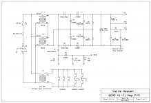
You certainly can use voltage multipliers with a transformer with a low volt secondary normally used for SS amplifiers. I have posted an amp design here (6CM5 hi-fi amp) which uses a voltage quadrupler. It has surprisingly good regulation providing the transformer rating and cap values are adequate. The rule of thumb is that the transformer secondary current rating divided by 4 for a quadrupler is the max current able to be drawn from the supply. I attach a power supply schematic for reference")
Attachments
Many thanks for the replies!
Sag and modulation are indeed my main worries with these form of supplies, but I also read in an earlier thread (from gcwills) that regulation can still be pretty good, even with a quadrupler. Furthermore the amp will be operating in rich class A, so the current draw from the supply is constant.
I have a copy of Valve Amplifiers (signed by Mr Jones!). I remember the part on diodes rating, but couldn't remember he also deals with multipliers: I will have a look when I am back home.
It was indeed the thread on the 6CM5 amplifier that reactivated my interest in the voltage multipliers. I just built up the version above as the intermediate voltages come in quite handy, but if it doesn't work I will give the 6CM5 quadrupler a try!
Erik
I'm looking to do the same, multiply 28V x 4 = 112v.
These amps are rated at 3 amps so plenty left if divided by 4. 730mA.
Your design has 2 x 33v transformers in series??
What would be the best design for 1 tranny to multiply it's voltage by 4? (planning to buy a lot of 5 of these for just 35 USD).
These amps are rated at 3 amps so plenty left if divided by 4. 730mA.
Your design has 2 x 33v transformers in series??
What would be the best design for 1 tranny to multiply it's voltage by 4? (planning to buy a lot of 5 of these for just 35 USD).
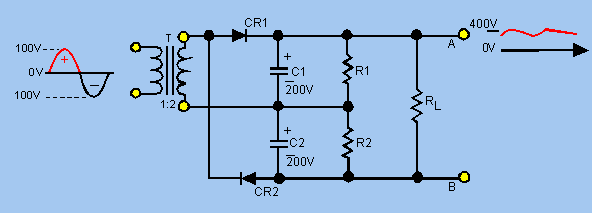
Just to clarify - in my multiplier example, 2 X 30V AC secondaries in series produces 60V AC RMS. When this is applied to the quadrupler, the resultant DC output is 60V RMS X 1.4 (the peak value of the 60V RMS voltage) multiplied by 4 = approx 360V DC no load, and loaded to 200mA (with these transformers and capacitors) the supply produces approx 310V DC.
Last edited:
so a 28v @3 amps:
28 x 1.4 = 39.2*4
= 156 volts @ 750mA
The maximum available DC current after rectification and filtering will be 750*0.7 = 525mA
Last edited:
The maximum available DC current after rectification and filtering will be 750*0.7 = 525mA
Thxs I wasn't aware of that losage.
still not bad 525mA. Enough to drive a lot of tubes.
Erik,
There a number of things one needs to take care of with voltage multipliers.
Often overlooked is the initial charging of the caps, as well as the possibility of overcurrent or short. In this case, the 'pumping' caps (in your case the outer vertical stacks) can become reverse polarized. Antiparallel diodes need to be used on them, and indeed even better, all caps. Diodes are really cheap so no excuse not to put them there.
Also, even though the stages of the multiplier are generally drawn in literature as having all the caps of the same value, in a setup such as yours, the charge moves up the ladder with each half cycle of the mains, but for each step the capacitance you see is actually smaller because looking from the trafo outputs, there are more and more caps in series. If you want to use additional taps from the multiplier, you have to account for the added current from the taps by increasing the capacitance of the capacitors below the tap.
Using capacitors as dividers (as in your +-70V supply) is NOT recomended. This means all the current from all the taps up and down passes through the divider and any change will upset the balance, including a possibility of getting the caps reverse polarized. This can be mittigated to an extent by increasing the capacitance valuse of those two caps, but it's really a patch - the principle itself is not sound. Your ground needs to be a fixed node in the multiplier, or you have to include some sort of active regulation there.
Other than this, assuming well dimensioned caps and diodes, the multiplier behaves very much like a transformer, but keep in mind that the rules of rectified and cap filtered AC from a transformer, still apply - in other words, you can never get the full VA rating of the transformer as Watts at the output - depending how the transformer is wound, it will be more like 50-70%.
As an aside, if you need to make an adjustable power supply by selecting a single tap of a voltage multiplier, you can set it up so that you can get more current out of the lower voltage taps, using the transformation-like effect of the multiplier. In this case, however, the capacitors need to be recalculated for equal energy storage at any given tap. A good approximation is to reduce the capacitance to half, with every successive stage of the multiplier.
I have never had luck with voltage multipliers over a voltage doubler circuit. Just too much ripple and sag. In order to make the multiplier work adequately too much other stuff has to be used overall, so it ends up being easier / cheaper to find the right transformer for the job.
With your 90vct transformer in a doubler circuit, you can get 250 and 125 volts at good regulation. Perfect for a 2A3 amp.
With your 90vct transformer in a doubler circuit, you can get 250 and 125 volts at good regulation. Perfect for a 2A3 amp.
As long as we're on the subject of voltage multipliers, is a Full-wave voltage doubler better than a Half-wave voltage doubler?
Thanks,
Ray
That's exactly what I was thinking. I saw this:
from here:
Voltage multipliers
If I had a 500VCT @ 150mA transformer, the normal full-wave output would be
250VAC rms * 1.4 = 350 VDC
Current would be 150mA * 0.775 (rms) = 116mA (? - not sure of that)
So a full-wave voltage doubler applied would yield 700VDC @ 58mA?
--
I believe you would have to look and see how the transformer is rated, but my understanding it's all about watts or va. At one point I had contacted Hammond about one of their transformers, they stated that even though the current rating of the transformer was for a full wave rectifier, if I used a bridge I could still get the same current. Tech support claimed their transformers are very conservatively rated.
- Status
- This old topic is closed. If you want to reopen this topic, contact a moderator using the "Report Post" button.
- Home
- Amplifiers
- Tubes / Valves
- voltage multiplier based on SS trafo - LONG