How is amperage affected when unwinding a secondary?
If I have 28v @ 3 amps and I want to reduce it to lets say 12.6 v by taking out some windings, what happens to the amperage?
Amperage on the primary or secondary? What I would do is unwind the secondary to get 12.6v. Then with the extra wire, wind the same amount of turns as the 12.6volt winding so you have 2 - 12.6 volt windings. Then you can parallel for twice the current or use them separately. IE. 2 x 12.6 volts @ 3 amps. Put a wrap of tape between the 2 12.6 v windings for isolation.
Daniel
Amperage on the primary or secondary? What I would do is unwind the secondary to get 12.6v. Then with the extra wire, wind the same amount of turns as the 12.6volt winding so you have 2 - 12.6 volt windings. Then you can parallel for twice the current or use them separately. IE. 2 x 12.6 volts @ 3 amps. Put a wrap of tape between the 2 12.6 v windings for isolation.
Sounds like a nice project. Yes the secondaries.
Got 4 to play with.
Might need some more explanation
")
I unwind little by little and keep measuring until I get 12.6?
Then how to I wind the extra wire back on?
If you are able to take apart the laminations so you can get the bobbin by itself, the easiest way to do this is to unwind the secondary and count how many turns it is comprised of. Take this number and divide by the secondary voltage and this will give you the turns per volt. For example, your secondary is 26.5 volts and the secondary has 79 - 80 turns. 79.5 / 26.5 = 3. So for every 3 turns of secondary, you get 1 volt on the secondary. So for 12.6 volts you need 3 X 12.6 = 37.8 or 38 turns.
Understand?
Daniel
Understand?
Daniel
If you are able to take apart the laminations so you can get the bobbin by itself, the easiest way to do this is to unwind the secondary and count how many turns it is comprised of. Take this number and divide by the secondary voltage and this will give you the turns per volt. For example, your secondary is 26.5 volts and the secondary has 79 - 80 turns. 79.5 / 26.5 = 3. So for every 3 turns of secondary, you get 1 volt on the secondary. So for 12.6 volts you need 3 X 12.6 = 37.8 or 38 turns.
Understand?
Great thxs.
Then I wind the second secondary over the the first with the same number of turns?
Thanks for all contributions!
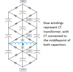
In the meantime I read the chapter on voltage multipliers in MJ and read and reread the post by ilimzn to grasp (I think) all of its content. The voltage multiplier diagram that inspired me at first is shown as attachment: I got it from tubecad (one of the last pictures) but I understand from the post by ilimzn that it is not really safe!?
For the moment I will use the schematic by gcwills!
The voltage multiplier diagram that inspired me at first is shown as attachment: I got it from tubecad (one of the last pictures) but I understand from the post by ilimzn that it is not really safe!?
I'm not sure that ilimzn's concern applies; he may have missed that the tranformer center tap is connected to the center of the cap "divider", which of course is not a cap divider in that case, and the transformer will protect the caps. I know that I missed that detail until you linked to the tubecad schematic, which is a bit clearer to me.
So I slept over it a couple of nights, and even if I eventually won't use this multiplier I want at least to fully understand its working. I redraw (second picutre) to hopefully make clear how the transformer is connected to the multiplier, as I recognize that my first drawing was not very clear.
I read MJ. He shows a half-wave version (just like the first picture), but I assume that the full-wave version is just a mirrored version of the half-wave, and so the same math apply. Well, MJ writes 'every diode needs a voltage rating > sqr root of 2 x Vin (RMS)... capacitor must be rated at > 2 x sqr root 2 x Vin (RMS)'. I have 45V RMS in each 'leg' of the multiplier, so the 1000V diodes I am using are fine! For the capacitors I get 2 x 1,41 x 45 = ~127V, so using 200V capacitors throughout should work fine!?
I still do not understand the 'anti-parallel diodes' on all capacitors. Wouldn't these just short out the capacitors?
many thanks, Erik
Attachments
I use the one in this schematic it sounds fine, note four different supply voltages in use. You can read stuff until your eyes are sore, but until you try something you won't know anything. Sure it's half wave rectification, sure people can run it down and say it won't work well, until you try it you don't know. I tried it and I know the circuit here works, and I wouldn't doubt for a moment gcwills quadrupler, the design he placed here only to help others.
Hi Ian444
You are right, and I also tend to judge based on my own experience and ears. I already built the multiplier shown in the post above and will test it (I wrote before that I may eventually not use it, this all depends on the results), I was just not sure about some technical aspects of it, such as the voltage ratings of capacitors and diodes: so I found out (still to be confirmed by the more experienced builders) that I can use 200V rated capacitors instead of 450V as I used in my first version. With other words, my questions are technical and not of the type 'how does a multiplier sound'.
The schematic you linked to is quite interesting: it is actually the same quadrupler as used by gcwills, but with 'taps' for additional voltages. I think the transformer winding is about 100V RMS?
Erik
Last edited:
Yes 100V rms. Rectify 100VAC and double it, or double the 100VAC and rectify it, same result. Voltage doublers have the rectification built in. Here's a little more info regarding voltage stress on caps. It depends on the type of doubler, you are right, there is not a lot of clear cut and dried info. Here is my cheat sheet
Great info guys.
I will experiment with these different circuits as I tried this and I could not get rid of a hum even with a cascode source on the anode and quite a lot of caps.
I added another 680u cap on this diagram, Even tried it on a SRPP circuit.
Maybe it was my heaters but never had noisy AC heaters. Maybe the heater bias was too low! Who knows?
Attachments
Thanks for the cheat sheet! It is a very handy one!
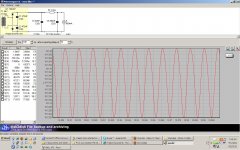
Yesterday evening I hooked the multiplier (as shown in the first post, using 100uF caps) to a Variac, used a 60W bulb as load to draw about 225mA and did some measurements on voltage drop. I calculated that the reactance of a 100uF cap at 50Hz is about 30 ohms. Still the current through the capacitor is not the constant 225mA, but higher, as the charge is done in pulses and not through a constant nice current... All with all the voltage drop with 100uF caps was too high, so I bought some 1200uF/200V caps (I know these are oversized, but they were the same price as the 470uF and 820uF) and once they arrive will experiment with them.
I also found some transformer with a single 90V secondary, so I will give the Menguye PS a try as well!
- Status
- This old topic is closed. If you want to reopen this topic, contact a moderator using the "Report Post" button.
- Home
- Amplifiers
- Tubes / Valves
- voltage multiplier based on SS trafo - LONG