Hi all - you may be aware of an amp I built several years ago found at Grant Wills
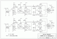
I continue to receive enquiries about this amp which was built to take advantage of speaker line transformers available here in Australia. I recently developed an alternative power supply based on voltage multipliers as normal hi voltage power transformers are not readily available in Aust. I particularly like the sound of this amp - 6CM5 or EL36 sound great in triode or ultralinear mode. As I recently created the schematics in ExpressSCH, I thought I'd post them here")
I continue to receive enquiries about this amp which was built to take advantage of speaker line transformers available here in Australia. I recently developed an alternative power supply based on voltage multipliers as normal hi voltage power transformers are not readily available in Aust. I particularly like the sound of this amp - 6CM5 or EL36 sound great in triode or ultralinear mode. As I recently created the schematics in ExpressSCH, I thought I'd post them here
Attachments
One main reason - the grids of the PI sit at 35V - DC coupling would compromise the biasing of the input stage.Grant, thanks for posting. One question- why do you RC couple between first and second stages rather than direct couple? This puts another rolloff in the open loop transfer function.
Really clever design Grant; I've used line level transformers myself with 6bq5's.
The difficulty in getting tube audio/power transformers in Aus sucks; I'd go as far as to say that unless you can afford to fork out the pretty ridiculous cash to have them custom wound or imported from the states (or to pay for someone else to have them inported), its the most difficult aspect of turning a tube design into an amp here in Australia.
Your use of commonly available parts might make tube audio a little more accessible for others.
Does AC coupling here introduce an extra LF rolloff? Everyone seems to think it does, but I disagree. The PS is essentially a differential amp, which amplifies the voltage difference between its two inputs. There is some common-mode gain too, but that will be much smaller. The differential amp has a resistor between its inputs, and this will form a high-pass filter with a coupling capacitor whichever side the capacitor is on. If there is a capacitor on both sides, as shown in this circuit, then it is simply the series combination of the two capacitors which counts. So still only one LF rolloff!
The PS common mode gain will complicate this but if small enough this should not affect LF stability.
The PS common mode gain will complicate this but if small enough this should not affect LF stability.
Does AC coupling here introduce an extra LF rolloff?
Yes it does. There are three LF zeros- the RC from voltage amp to phase splitter, RC from phase splitter to output tubes, and the output transformer. If you're not convinced of that, think of it this way- will DC drift in the first stage tube affect the output stage bias?
If you DC couple from the input amp to phase splitter then you still have 3 LF rolloffs because the capacitor to ground from the 'other' PS grid introduces one. This is the one people don't notice. My point was that this is not necessarily an extra one, but combines with the first one. Some people claim that DC coupling eliminates a rolloff; even Mullard seemed to get this wrong.
DC drift in the first stage only propagates through the common-mode gain of the phase splitter if DC coupled, and not at all if AC coupled. But it will be common-mode at the PS anodes too whereas the signal is differential. The drift will cancel in the OPT so will not affect LF stability.
Going back to AC, what happens at the other grid? There is a low-pass filter, which keeps the grid steady at the same average voltage as the PS input grid. What if the signal is so slow that the grid starts to follow? Then you can see that this LP filter causes the PS to have a high-pass action. Is this an extra rolloff?
DC drift in the first stage only propagates through the common-mode gain of the phase splitter if DC coupled
Yes, that seems right. You'd have to put a DC voltage source on that second grid to eliminate the zero. Thanks!
As I recently created the schematics in ExpressSCH, I thought I'd post them here
There is an error in your schematic - I believe the other ultra-linear connection (the one belonging to the upside-down output tube of each channel) should go to 10W tap on the transformer to keep in line with arrangement above where UL is at 50%.
15W tap should be left unused.
There is an error in your schematic - I believe the other ultra-linear connection (the one belonging to the upside-down output tube of each channel) should go to 10W tap on the transformer to keep in line with arrangement above where UL is at 50%.
15W tap should be left unused.
The schematic is correct - for more info on the M1115 see here: http://home.alphalink.com.au/~cambie/6AN8amp/M1115.htm
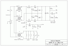
I'm very interested in this power supply. I'm wrong or you reach to extract more than 300VDC, from a 60VAC assy made of two 0-30 secondaries in series?
Are these 0-30 VAC 2A each?
Hi - thanks for your question - the combined 60V (@1A) is fed into a voltage quadrupler producing about 310V DC under load of 250ma. This approach allows us here in Aust to build high voltage supplies with a very limited range of power transformers.
Really clever design Grant; I've used line level transformers myself with 6bq5's.
The difficulty in getting tube audio/power transformers in Aus sucks; I'd go as far as to say that unless you can afford to fork out the pretty ridiculous cash to have them custom wound or imported from the states (or to pay for someone else to have them inported), its the most difficult aspect of turning a tube design into an amp here in Australia.
Your use of commonly available parts might make tube audio a little more accessible for others.
Thanks for your kind comments - yes, when you compare the low costs of say a 30V 1A or a M1115 transformer here in OZ compared with imported transformers it makes a big difference to the final cost of any amp constructed
The schematic is correct - for more info on the M1115 see here: http://home.alphalink.com.au/~cambie/6AN8amp/M1115.htm
I stand corrected !
Hi - thanks for your question - the combined 60V (@1A) is fed into a voltage quadrupler producing about 310V DC under load of 250ma. This approach allows us here in Aust to build high voltage supplies with a very limited range of power transformers.
Have you considered using isolation transformers? (230V - 230V)
They are used in the industry, and can (at least here) be found pretty cheap.
Otherwise, good work
Thanks for your suggestion re 230v to 230v isolation transformers - I wish they were readily available here in Oz, but they are only available at a high cost for TV service work unlike your situation in your country. The only cheaper option here is 240v to 110v stepdown transformers, but most of them are not isolated but are autotransformers and unsuitable. So the only cheap option here are transformers used here in large quantities suitable for solid state applications - ie low voltage high current. I have used the multiplier supplies successfully for numbers of builds and the regulation holds up surprisingly well
Last edited:
- Status
- This old topic is closed. If you want to reopen this topic, contact a moderator using the "Report Post" button.
- Home
- Amplifiers
- Tubes / Valves
- 6CM5 hi-fi amplifier