Zero.
Not zero, but small.
If you look at figure 4 in the Metson (1952) paper, the effect of soft x-ray is a minor deviation of the vacuum curve at extremely minuscule (pA) currents.
The contribution of these current is small, for sure. Especially with gassy NOS, or gassy new production, or even if you operate at normal heater voltage. 
There is one documented application where ambient light does corrupt valve operation, though - Electrometer triodes!
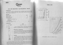
See the GEC data for the ET3: 'Operating Conditions'
'valve should be operated in darkness'.
That's if you want your 10fA grid current, anyway.
I'll accept the word of a GEC/OSRAM data sheet as authoritative on that much.
There is one documented application where ambient light does corrupt valve operation, though - Electrometer triodes!
See the GEC data for the ET3: 'Operating Conditions'
'valve should be operated in darkness'.
That's if you want your 10fA grid current, anyway.
I'll accept the word of a GEC/OSRAM data sheet as authoritative on that much.
Attachments
So if light can affect cathode emission, will my preamps with >80dB gain register a flash from my camera's strobe if I shoot at them from close range?
Gotta try it.
If not, can we still waste time worrying about photons?
Actually, I did that experiment (though was really looking at the effect on cathode bias LEDs, but the tube was right there) a couple years ago and posted the results. As you might guess... no measurable effect.
So if light can affect cathode emission, will my preamps with >80dB gain register a flash from my camera's strobe if I shoot at them from close range?
Gotta try it.
If not, can we still waste time worrying about photons?
I'm not saying you need worry about photons in a normal, practical amplifier.
The illustration is only there for those that don't accept the fact that the effect occurs at all - should anyone really be thinking so.
If you want to measure a photo flash event (in grid current terms), you must start with a grid current of, say, 10pA or less. Good luck finding some valves to fit that socket!
Most grids are made from molybdenum, which has a work function of 4.6eV.
Dividing by planck's constant, the threshold frequency of the photons for is therefore 1.1 E15 Hz, or 270nm wavelength.
This is UVc light, so it is entirely possible for UV and soft X-rays from the anode to cause photoelectric emission. Please check your physics before posting!
(The work function of the copper side rods is 4.7eV, which also has a threshold frequency in the UVc range)
Now, let's continue checking your physics and calculate impact of ionization of gases. Then compare results of calculations to empirical data.
That's not checking my physics, that's just adding more variables. In a gassy valve, gas current can easily be expected to dominate.Now, let's continue checking your physics and calculate impact of ionization of gases.
In a gassy valve, gas current can easily be expected to dominate.
That's my point, exactly: "in glass valves...", the rest is the same. I even don't mean energy of absolute vacuum that use modern physics; I mean a real vacuum in real tubes.
My diversion through electrometer triodes turned up something even more relevant, if we care to go back to the original question of the thread.
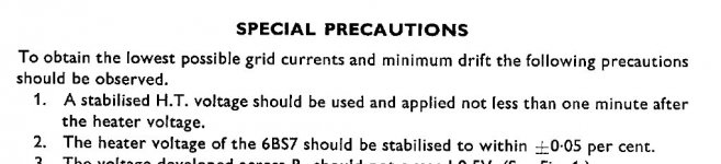
The attached extract is from the BRIMAR (Footscray, Kent) data for the 6BS7 pentode, a nice audio valve, that doubles as an electrometer tube, when selected samples were used.
See the precautions for electrometer use:
1. A Stabilised HT must be used and applied not less than 1 minute after the heater voltage.
The only reasonable conclusion we can draw from this warning being issued for electrometer applications is that grid current will not remain low if you ignore it.
The only explanation on the table for increased grid current in crash-started amplifiers is -
the van de Weijer effect.
A blob of emissive material splats onto your grid, for every crash-start.
Attachments
The only reasonable conclusion we can draw from this warning being issued for electrometer applications is that grid current will not remain low if you ignore it.
The only explanation on the table for increased grid current in crash-started amplifiers is -
the van de Weijer effect.
A blob of emissive material splats onto your grid, for every crash-start.
There's one important one you're missing- anode composition. Some anodes are made with built-in gettering (e.g., 6528, 6336) which MUST be heated before application of voltage. Those are exceptional tubes and this requirement is spelled out on their datasheets.
For electrometer service, the pico-amp stuff that we can neglect for all other uses becomes much more important- for example, they also specify that the tube be operated in the dark and that it be conditioned for 200 hours.
There's one important one you're missing- anode composition. Some anodes are made with built-in gettering (e.g., 6528, 6336) which MUST be heated before application of voltage. Those are exceptional tubes and this requirement is spelled out on their datasheets.
I'm not missing anything in that regard!
There's a Brimar 6BS7 right here with me now, and it assuredly has the usual halo getter ring and deposit.
It's actually an audio pentode, after all.
That says nothing about the plate composition- a 6528 or 6336 also has a conventional getter. The gettering as part of the plate is an extra means of keeping the gas low.
Why would a 1mA low-noise pentode take its anode design from a heavy-duty pass-regulator tube?
That says nothing about the plate composition- a 6528 or 6336 also has a conventional getter. The gettering as part of the plate is an extra means of keeping the gas low.
SY, are you referring to the zirconium coating on the plate or the graphite itself acting as a getter? I always assumed the Zr was there to reduce secondary emission.
The 6528 data specifies a cathode conditioning period of thirty seconds due to the peculiarities of a series pass regulator circuit. See note 13 on page 3 of the Raytheon data sheet.
John
Last edited:
...so you finally agree that we can apply HT at the same time as the heaters! Great, now we can post our conclusion and build happily here after
Haven't you had enough yet?
OK, Let's go back to your post #1 where you tell us that the book by Merlin Blencoe (would that be the Merlin here?) converted you to the Crash-Start school of design.
The author claims:
If you're wondering why all those old amps use a standby switch, its because they were designed on the cheap. The power supply caps would usually be rated only for the working voltage, not the peak voltage which occurs before that valves start drawing current. Leo Fender, and the rest, relied on the musician to use the standby switch to stop those caps bursting. The rest is history. Nowadays no designer (who values his reputation) uses underrated capacitors, so the standby switch has become obsolete, but your average amp tech doesn't know this.
This claim is directly contradicted by almost every guitar amp maker.
Hartley Peavey even wrote a paper "Standby for the Truth" to demonstrate that Cathode Stripping was the reason his amps are fitted with a switch:
The early rectifiers used “directly heated cathodes” (which were themselves, merely the heater filaments coated with a barium/strontium oxide). They produced output voltage VERY RAPIDLY when turned on. Since these directly heated cathodes were often used to power other tubes (valves) whose cathodes were “INDIRECTLY HEATED,” a problem arose when the full plate voltage (B+) was applied BEFORE the “indirectly heated” cathodes of
the audio amplifier’s tubes reached their operating temperature. When the full high voltage (B+) is applied significantly BEFORE a tube reaches operating temperature, the cathode coating can be “stripped” of its ability to
emit electrons. This destructive process is called “cathode stripping” and it is mainly for THIS REASON that so-called “standby” switches were provided on numerous electronic devices using DIRECTLY HEATED RECTIFIERS (with INDIRECTLY HEATED TUBES for operation)!
going on to say:
Most musicians WRONGLY assume that the standby switch is provided primarily to disable the amplifier in such a way as to provide instantaneous operation by switching on the “standby” switch. Some even refer to this
switch as a “beer button” to cut off the amp during breaks in a performance. Unfortunately, this very widely held MISCONCEPTION can (and does) cause problems. The nature of these problems should be understood if one wants to maintain optimum tube life and performance for as long as possible.
As stated above, standby switches have more or less become an “expected feature” of modern tube instrument amplifiers. In many cases, these so-called “standby” switches are provided only because they are “expected” to be there. One should always be aware that the REAL reason the standby switch is provided is to switch OFF the high voltage (B+) UNTIL the tubes reach their FULL OPERATING TEMPRATURE, so as to avoid “cathode stripping” of the indirectly heated cathodes of the preamp and output tubes.
Fender have an article to the same effect:
Fender News:The Standby Switch
Fender News:The Standby Switch
Therein lies the real utility of the standby switch. It allows the amp to be turned on but keeps full voltage from reaching its power tubes until they’ve had sufficient time to warm up, thus protecting them and prolonging their life.
MESA-BOOGIE, from the Studio Caliber manual:
Marshall, from the DSL manual:
POWER-UP:
Connect your favorite guitar to the instrument input jack. Turn the power switch "On" while leaving the standby switch set to "Standby". It’s always a good idea to practice this start up procedure as at least 30 seconds of warm-up time lessens the shock on cold power tubes, thus prolonging their life substantially.
Marshall, from the DSL manual:
11. Standby Switch
This turns the high voltage feed to operate the
valves on and off.
✪ User Hint - This switch should be used for
(a) allowing the amp to warm up before turning
the Standby on (at least a minute - preferably 2/3
minutes if possible) and (b) turn the Standby
switch off when taking a break (rather than
turning off the whole amp), thereby keeping
your amp at the ‘ready’, without waiting for it to
warm up again. Remember to do these two
simple rules and your valves will love you for it
and should last an awful lot longer before
replacement is needed.
To be blunt, all of those articles are nonsense. They were either written by people who themselves were brought up with the same cathode-stripping misinformation as a world of guitarists, or they are written by marketing folk. They do not 'demonstrate' anything, they simply re-state the myth and help deluded customers feel better about themselves. Since soft start is unlikely to do any harm, who is going to challenge them? Only scientific pedants, and who cares about them, they're not bringing in the dollars. No company would ever write "the standby switch is to stop our underrated capacitors from blowing up" or "we don't know what the standby switch is for, we just copied it from some older amps". Remember, just saying something over and over again does not make it true, it only makes it received truth, or perhaps religion.Haven't you had enough yet?
Hartley Peavey even wrote a paper "Standby for the Truth" to demonstrate that Cathode Stripping was the reason his amps are fitted with a switch:
So far no one has presented a shred of evidence to suggest that the delayed application of the HT gives any extension of the working life, or that a shock start has any deleterious effects, in receiving valves.
Electrometer use is very different from normal use of course (5pA grid current is astonishingly low!) but I will do my best to hunt out the science behind the 6BS7 datasheet advice; it must exist, unless it was only a precautionary measure they added 'just in case'.
Last edited:
To be blunt, all of those articles are nonsense. They were either written by people who themselves were brought up with the same cathode-stripping misinformation as a world of guitarists, or they are written by marketing folk.
Er, I carefully began with Hartley Peavey, because he founded Peavey Electronics in 1965, making amps HE DESIGNED. He is not a marketeer.
If you think that the Founder and original designer of Peavey amps is ignorantly making claims about the proper use of amps he designed, then the onus is on YOU to substantiate what you say.
This is conspicuous by its absence.
- Status
- This old topic is closed. If you want to reopen this topic, contact a moderator using the "Report Post" button.
- Home
- Amplifiers
- Tubes / Valves
- Lets settle the b+ on cold tubes issue!