"On cap value. Its true that a film cap is equal to double or triple the value of electrolytic, right?"
No 1uf is 1uf. It doesn't matter what kind of cap it is. Whats different is the dialectric and how it affects how the cap charges and discharges, the ESR and leakage. While I agree that this makes a difference in the signal path of the amp, in a power supply upstream of a properly functioning regulator it should not make a detectable difference.
If you just remove the choke you will gain the 10 volts dropped by the choke. The 60uf cap used as the only filter on the input of the regulator will increase the input voltage to the regulator by about 30 volts. At that time the ripple into the regulator @ 12ma current to the load will be less that 2 volts. You have gained 40 volts for the regulator to work with. The regulator now that it has the headroom to work with will reduce the ripple to a few millivolts and be stable.
Try removing the choke. Just try it.
BZ
This board is my school so when I mention something its with an ear to learn. Thanks for hanging with me. Whatever I learn I try to pass on to others.
For example, the original schematic was CRC. Each cap was 330uF. I replaced the second cap with the 60uF film cap. No drawback and a lot of improvements. I was skeptical but it worked. 60uF was better than 330uf electrolytic in this case. 1/5th the value - which lead to a statement for clarification above.
By adding the choke the PSU stiffened up and the speed and bass response was better. The body of the music was much better.
Then I couldn't get enough voltage so I went to OA2 which provided it.
So while soundwise things were going great I didn't know I had built a time bomb which finally went off when I went up in voltage/current.
I now realize I have two conflicting parts to the PSU. As mentioned in the beginning I decided to ditch this overly complex regulated supply and just go for straight unregulated.
I'll try removing the choke. The only reason I hesitate is the great improvements the choke provided. This has been a 1.5 year process which I carefully documented. I know what the PSU sounded like with each change.
aardvarkash10 - I'll model it using 20mA which should be enough headroom and email the PSU file.
Thanks again everyone. I know its hard to troubleshoot over the internet. This board is the best DIY site I've ever been on.
very worthwhile reading on the subject from Steve Bench.
Note the pass tube is a TV line output tube - excellent choice as they have high current at low (relatively) voltage capability.
Note the pass tube is a TV line output tube - excellent choice as they have high current at low (relatively) voltage capability.
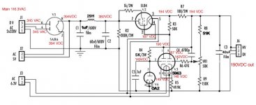
There are several problems with this circuit. The basic PSU is half-way between choke input and capacitor input - this could make it less stable than either of those would be.
R4 is too large, as the 0A2 needs a minimum current of 5mA (max 30mA). VR tubes can do strange things when used outside their specification. R4 should be between 3K and 8K. Alternatively, move the top end of R4 to C2 or go back to a lower voltage VR tube. C5 at 0.1uF is right on the upper limit for stability; I would be tempted to reduce it to 0.047uF.
The top end of R3 should go the anode of the EL84, not the cathode. As it is, V3 right-hand side is almost cutoff so with C4 providing feedback there is always a risk of some type of relaxation oscillation. If present, this would get worse at higher output voltages as V3 is then nearer cutoff. Does it still oscillate if C4 is removed?
C3 should not be needed, or should be much smaller. Putting a heavy capacitive load on what is essentially an amplified cathode follower is asking for trouble.
Stabilised power supplies are servo systems, with heavy feedback. In order to design one you need to know what Mr. Nyquist and Mr. Bode say about stability. If not, just copy a good design and don't change it.
DF96. Thanks for the very detailed analysis. I'll get right on it. Confirms what others have said and I do appreciate it. ")
C4 has been removed. If you look at post #1, #8 that is the present layout with #8 being the latest voltages. Interesting on C3 as other mentioned this. I'll try just removing it and then something smaller. Originally it was designed for a 47uF. Think I should go even smaller if I decide it affects the sound?
Very interesting comment on R3.
Last edited:
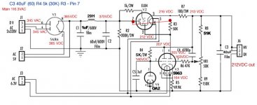
I want to do this one step at a time for learning purposes. I know everything is relational. I changed R4 to 5K and gained 1VDC. I also changed C3 to 40uF from 60uF. That resulted in a 5VDC drop in output voltage.
If I move R4 to C2 I'm also affecting the grid of V3. New voltages attached.
If I move R4 to C2 I'm also affecting the grid of V3. New voltages attached.
Attachments
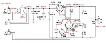
I now moved R3 to the plate from the cathode. All voltages are up. Output increased 12VDC appx
The VR tube is still current starved but I don't understand how its dropping so much voltage with just a 5K resistors. All voltages attached.
I sensing I burned everyone out. Sorry if I have.
The VR tube is still current starved but I don't understand how its dropping so much voltage with just a 5K resistors. All voltages attached.
I sensing I burned everyone out. Sorry if I have.
Attachments
The VR tube is still current starved but I don't understand how its dropping so much voltage with just a 5K resistors. All voltages attached.
Its dropping exactly what ohms law tells it to. Supply to the top of the 5k resistor is at around 200V. The VR tube drops 150, so the voltage drop accross the resistor is the difference ie 50V more or less. 50V/5000ohm = 0.01A
And no - us southern hemisphere guys are still around, learning right alongside you!
Last edited:
no - your maths sucks worse than mine.
As above, you are dropping around 50 volts across the 5k resistor. Hence the current in the VR circuit MUST BE 50/5000 = 0.01A or 10mA
So, if the whetting current of the VR is 5mA minimum, that part is now ok.
Some of your other measured voltages look distinctly odd though - 7 volts difference from one end of a wire to another? (pin 2 of the EL84 to pin 6 of the 5963)
Last edited:
No - refresh your browser and you will see I 'fessed up to a math error in post 52. Your friend is around the mark - by my calculation you are running approximately 10mA in the reference circuit. That part is all good now, so stick with the 5k resistor for hte moment.
R4 is dropping 61 Volts, 207-146=61. R4 is 5000 Ohms. 61/5000=.0122 or 12.2ma. Both the resistor and VR tube are in series, current thru a series circuit is the same thru all components. If there is 12.2 ma thru the resistor so it must be thru the VR tube as well. Clear as mud now right?
Craig
Craig
- Status
- This old topic is closed. If you want to reopen this topic, contact a moderator using the "Report Post" button.
- Home
- Amplifiers
- Tubes / Valves
- Oscillating PSU above certain voltage