I was going to tack this on the end of the gimp's thread but thought i might dilute or derail it.....
I am not really sure or confident of what I am presenting here, so I am asking for some idea of the rightness or wrongness of this approach to measuring amplifier harmonic distortion. I have found some articles on the net but they all seem to point to expensive test equipment or an array of notch filters, cumbersome or expensive.
I have constructed a clamp/buffer so that I can safely feed the amp output into a cheap pc soundcard. After a few trials I elected to use roughly 3:1 voltage divider in the buffer so that 2.83 volts across 8ohms(1 watt) from the amp, produced 0.775vrms(0db) into the soundcard.
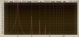
feeding a 1k signal from the sig-gen into the amp I measured the harmonic spectrum using a spectrum analyser(in this case the span vst plug from voxengo) and produced the chart shown.
Taking the dbu values of the harmonics shown I converted them into rms voltages(dB dBu dBFS dBV to volts conversion - calculator volt volts to dBu and dBV dB mW - convert dB volt convertor converter calculation online attenuation loss gain ratio reference audio engineering sound recording dBFS dBVU 0 dB audio logarithm level con), added them up, and then found the total as a percentage of the fundamnetal, i.e 0.775v i.e 0db.
from the example shown, which is a 2A3 with 6sl7 srpp driver, I found the following values:
F2....-39dbu-----0.008 vrms
F3....-49dbu-----0.002 vrms
F4....-68dbu-----0.0003 vrms
F5....-81dbu-----0.00006 vrms
giving a total of 0.01036 vrms which I think is about 1.33% thd
given the innacuracies of the equipment, does this sound like a valid method to get a rough figure for thd.
Ed
I am not really sure or confident of what I am presenting here, so I am asking for some idea of the rightness or wrongness of this approach to measuring amplifier harmonic distortion. I have found some articles on the net but they all seem to point to expensive test equipment or an array of notch filters, cumbersome or expensive.
I have constructed a clamp/buffer so that I can safely feed the amp output into a cheap pc soundcard. After a few trials I elected to use roughly 3:1 voltage divider in the buffer so that 2.83 volts across 8ohms(1 watt) from the amp, produced 0.775vrms(0db) into the soundcard.
feeding a 1k signal from the sig-gen into the amp I measured the harmonic spectrum using a spectrum analyser(in this case the span vst plug from voxengo) and produced the chart shown.
Taking the dbu values of the harmonics shown I converted them into rms voltages(dB dBu dBFS dBV to volts conversion - calculator volt volts to dBu and dBV dB mW - convert dB volt convertor converter calculation online attenuation loss gain ratio reference audio engineering sound recording dBFS dBVU 0 dB audio logarithm level con), added them up, and then found the total as a percentage of the fundamnetal, i.e 0.775v i.e 0db.
from the example shown, which is a 2A3 with 6sl7 srpp driver, I found the following values:
F2....-39dbu-----0.008 vrms
F3....-49dbu-----0.002 vrms
F4....-68dbu-----0.0003 vrms
F5....-81dbu-----0.00006 vrms
giving a total of 0.01036 vrms which I think is about 1.33% thd
given the innacuracies of the equipment, does this sound like a valid method to get a rough figure for thd.
Ed
Attachments
Last edited:
-40 dB (compared to the fundamental) corresponds to 1% distortion,
so your math seem to be about right.
If you have not already done so, you should also make a measurement of the output from the tone generator so you know the source distortion and thus your measurement limits.
In order to know the exact level of the measurement, I find it practical to use a good multimeter on the output, since calibrating the soundcard with attenuator and input volume control is a bit unpractical.
Svein.
Last edited:
Hi Svein
thanks for the look, and thanks for the basis of the clamp/buffer, it was your circuit I started with.
I did calibrate the i/p to the sound card with a dmm, but my dmm is more suspect than my maths.....but 0.775 in did indeed present 0db at the s/w input.
I ran the sig gen(Farnell LFM4) through before I started and all I could get was the fundamental on the chart, right down to -110......
Ed
I was going to tack this on the end of the gimp's thread but thought i might dilute or derail it.....
I am not really sure or confident of what I am presenting here, so I am asking for some idea of the rightness or wrongness of this approach to measuring amplifier harmonic distortion. I have found some articles on the net but they all seem to point to expensive test equipment or an array of notch filters, cumbersome or expensive.
I have constructed a clamp/buffer so that I can safely feed the amp output into a cheap pc soundcard. After a few trials I elected to use roughly 3:1 voltage divider in the buffer so that 2.83 volts across 8ohms(1 watt) from the amp, produced 0.775vrms(0db) into the soundcard.
feeding a 1k signal from the sig-gen into the amp I measured the harmonic spectrum using a spectrum analyser(in this case the span vst plug from voxengo) and produced the chart shown.
Taking the dbu values of the harmonics shown I converted them into rms voltages(dB dBu dBFS dBV to volts conversion - calculator volt volts to dBu and dBV dB mW - convert dB volt convertor converter calculation online attenuation loss gain ratio reference audio engineering sound recording dBFS dBVU 0 dB audio logarithm level con), added them up, and then found the total as a percentage of the fundamnetal, i.e 0.775v i.e 0db.
from the example shown, which is a 2A3 with 6sl7 srpp driver, I found the following values:
F2....-39dbu-----0.008 vrms
F3....-49dbu-----0.002 vrms
F4....-68dbu-----0.0003 vrms
F5....-81dbu-----0.00006 vrms
giving a total of 0.01036 vrms which I think is about 1.33% thd
given the innacuracies of the equipment, does this sound like a valid method to get a rough figure for thd.
Ed
I'm pretty sure that THD is the power sum of the harmonics, not the voltage sum.
The power sum would be obtained by summing the squares of the RMS voltages (power = voltage ^2), then taking the square root of that to get back to RMS voltage to calculate THD. In your example it should work out to about 1.06% THD
Cheers,
Michael
The valid method is to observe spectrum in dynamics and decide is it "natural" or "alien" to our perception: from very low to the max output. For the reference, "natural" spectra are results of non-linearities in an air, wood, stone, and so on, depending on degree of excitation.
THD is like an average temperature of patients in the clinic: it may be used to determine what kind of clinic is it. But can't provide an information about conditions of each of patients, and what they need to be healthy.
THD is like an average temperature of patients in the clinic: it may be used to determine what kind of clinic is it. But can't provide an information about conditions of each of patients, and what they need to be healthy.
[snip]I have constructed a clamp/buffer so that I can safely feed the amp output into a cheap pc soundcard. After a few trials I elected to use roughly 3:1 voltage divider in the buffer so that 2.83 volts across 8ohms(1 watt) from the amp, produced 0.775vrms(0db) into the soundcard.[snip]Ed
Hi Ed,
What 'clamp/buffer' did you use? If it is some form of diode clamp, the distortion of that can easlily swamp the amp distortion.
It would be best to use the resistive 1:3 divider only (and just be carefull with that level control
") ).
).jd
Notice: Never leave a reference or comments off graphs..it's the quickest way to loose relevance to nothing. Put text on it.
On amplifier testing I always refer to full o/p as a 0dB ref (an old RF habit)with text details on side. Remember dB scales mean nothing without a reference to what is referrring to. (be clear)
Fractional dB scales are a pain in the a'se and aren't necessary. Power Scaling on 10dB/div on graticule is convenient; the rule of thumb becomes a doddle to work out... in this way, 60dB down becomes a thousanth, so as the ref is 100% then 60dB down must be 0.1%. Simple ! So if you study this more closely one can arrange work in display graticule sections of 10dB:-
100%,= 0dB
30%,=-10dB
10%,=-20dB
3%, =-30dB
1%,=-40dB
0.3%,=-50dB
0.1%.=-60dB
and so on, off by heart.
So picking off harmonics and knowing roughly the level should be kids play.
The example graph is an example.
I always work in plain dB and add the comprehendible rest to what one uV/V etc one is referring to.
Remember; on soundcards or digital scopes with FFT spectrum options, the setup is important. When asking it distortion % measurements there may be a box "harmonic detector" with a pull down 1-8. If one is using an old analogue thd meter, then it will be averaging to the
3rd any perhaps no higher. To get close to the similiar result, select the same.
The results will never be identical from one equipment to the another but be in the same ballpark.
I hope I've left no-one confused, but it's darned simple when you know how.
Everyone on the bench should also know the rule of thumb reactance of a 0.1uF cap at 1Khz = ~1600 ohms. From this one can figure out all the other combinations.
richy
Hi Ed,
What 'clamp/buffer' did you use? If it is some form of diode clamp, the distortion of that can easlily swamp the amp distortion.
It would be best to use the resistive 1:3 divider only (and just be carefull with that level control
jd
hi Jan
at the moment I've got opposing 2.4v zeners across the bottom leg of the divider. I will remove them and see if changes the figures.
thanks for the tip
Ed
The valid method is to observe spectrum in dynamics and decide is it "natural" or "alien" to our perception: from very low to the max output. For the reference, "natural" spectra are results of non-linearities in an air, wood, stone, and so on, depending on degree of excitation.
THD is like an average temperature of patients in the clinic: it may be used to determine what kind of clinic is it. But can't provide an information about conditions of each of patients, and what they need to be healthy.
Totally.
Do you know of a way to put perceptual naturalness on a scale?
Other than -- you know it when you hear it...
Degree of similarity to natural acoustic phenomena?
Does clarinet music sound better than flute music played through an amp that has odd harmonic distortion? Odd harmonics are natural for clarinet but lacking in flute tones.
I have a Hammond organ that allows me to add any amount of harmonic (distortion) to the notes. It has a slider control (drawbar) for each harmonic, even ones and odd ones, high ones and low ones. It even has extra 2f and 3f you can add just to the note attack. Everything sounds just like a hammond organ, naturally ;-)
As you say, the spectrum "in dynamics" i.e. as the spectrum changes with level and maybe "attack", has a more profound influence on the perception than the steady state distortion at some constant level. Given this, there shoud be dynamic spectrum testing methods.
How about using music as a test signal? Some techniques could be developed to use real music instead of simple periodic waveforms.
Totally.
Do you know of a way to put perceptual naturalness on a scale?
Something similar to F&M experiments may be used.
Change behavior of non-linear system in order to find thresholds of audibility of distortions in dynamics. Some amp with dials, like a specialized synthesizer. But how to build then the control amp, if we speak of very subtle differences? The control amp itself must be the synthesizer.
Other than -- you know it when you hear it...
...or don't hear. Subconscious reactions are more significant indicators than conscious judgment of degree of clearness.
for those that might be interested I've documented the above approach here:
www.vitalstates.org/diy/amplifiers/simple-thd-measurement.pdf
its not the most precise method but its got to be close to the cheapest for those with a limited budget.....
Ed
www.vitalstates.org/diy/amplifiers/simple-thd-measurement.pdf
its not the most precise method but its got to be close to the cheapest for those with a limited budget.....
Ed
Nice write up.
I guess the remaining question in my mind is "at what level do harmonics become noticable" (yes, this breaks down into odd vs even, and lower order vs higher order).
As Waveborn points out these may be 'perceived' without actually being aware that we 'hear' them.
I guess the remaining question in my mind is "at what level do harmonics become noticable" (yes, this breaks down into odd vs even, and lower order vs higher order).
As Waveborn points out these may be 'perceived' without actually being aware that we 'hear' them.
- Status
- This old topic is closed. If you want to reopen this topic, contact a moderator using the "Report Post" button.
- Home
- Amplifiers
- Tubes / Valves
- harmonic distortion