A speaker is inductive so will present a very different load.
Some speakers can be quite high impedance higher up the frequency range.
When I test my new amps I power it up with the output connected to a scope and with no speaker connected. I check for a DC offset and/or oscilation.
I then set the dc offset on a preset.
I the apply a sine wave with a speaker connected and turn up the bias slowly until crossover distortion goes.
Hi Folks,
Just a quick technical question - when looking at an amplifier output signal on a 'scope, does matter if the amplifier is connected to a speaker or dummy load? Specifically, will the trace be identical for the same test signal sine wave?
Cheers,
ob
No, it will not. That assumes you are comparing a non-inductive resistor to a typical loudspeaker.
The reason for that is, loudspeakers are inductive and the real impedance seen by the amp fluctuates with frequency due to changes in the inductance of the driver with frequency.
A non-inductive load is the best way to test an amp because the impedance is constant across the audio spectrum and provides a good benchmark to measure an amp that is consistent from amp to amp.
The other advantage is if the amp goes into oscillation or in the case of a transistor amp shorts to a rail, it may fry the resistor, but that is a lot cheaper than a loudspeaker.
I don't know about you, but I don't fancy having to listen to a full amplitude 1kHz sine wave (maximum power test) or even a low-level 1kHz square wave (stability test), let alone a full power 10kHz sine wave (slew rate test) that would probably quickly fry a tweeter.
And, as the others have pointed out, a true resistive load might not be representative of a real loudspeaker, but it's definitively and repeatably unrepresentative.
And, as the others have pointed out, a true resistive load might not be representative of a real loudspeaker, but it's definitively and repeatably unrepresentative.
Ever listen up close to 20W 1kHz Sine Wave on a 90 dB speaker. After a few minutes there won't be a need for HiFi.
A non-inductive resistor is the way to go. If you want to simulate real life then simulate it with a dummy load that doesn't change after a few seconds of power like speaker does and can be repeated.
The signal will not be the same.
A non-inductive resistor is the way to go. If you want to simulate real life then simulate it with a dummy load that doesn't change after a few seconds of power like speaker does and can be repeated.
The signal will not be the same.
Along the lines of this discussion, I have tried to source some reasonably priced high wattage 8R resistors, but my usual sources are always out of stock. I do have a pair of 6R 50W that I have been using. Is this going to induce big errors in my testing?
G'Day Rob, I have moved again and I am literally just around the corner from you now if you feel like sharing ideas over a beer or need to use any of my equipment!
Chris
G'Day Rob, I have moved again and I am literally just around the corner from you now if you feel like sharing ideas over a beer or need to use any of my equipment!
Chris
Both.
A dummy load as an attenuator for a speaker.
I have a lot of 20 Ohm resistors. If to connect 5 of them in parallel it is 4 Ohm in total, for higher power. If to add computer fans for forced cooling they will dissipate even more power without a problem.
http://wavebourn.com/forum/download.php?id=437&f=7
http://wavebourn.com/forum/download.php?id=438&f=7
A dummy load as an attenuator for a speaker.
Along the lines of this discussion, I have tried to source some reasonably priced high wattage 8R resistors, but my usual sources are always out of stock.
I have a lot of 20 Ohm resistors. If to connect 5 of them in parallel it is 4 Ohm in total, for higher power. If to add computer fans for forced cooling they will dissipate even more power without a problem.
http://wavebourn.com/forum/download.php?id=437&f=7
http://wavebourn.com/forum/download.php?id=438&f=7
Both.
A dummy load as an attenuator for a speaker.
I have a lot of 20 Ohm resistors. If to connect 5 of them in parallel it is 4 Ohm in total, for higher power. If to add computer fans for forced cooling they will dissipate even more power without a problem.
http://wavebourn.com/forum/download.php?id=437&f=7
http://wavebourn.com/forum/download.php?id=438&f=7
That looks serious!
Fortunately, most of my stuff has been low power. I have 6R aluminum clad 50W mounted on a heatsink because I found them at an electronics surplus place cheap. Every time I try for 8R or 4R they are not there. I could bite the bullet and buy some from RS when I place my next order, but being cheap, if the 6R is OK I won't bother.
I don't know about you, but I don't fancy having to listen to a full amplitude 1kHz sine wave (maximum power test) or even a low-level 1kHz square wave (stability test), let alone a full power 10kHz sine wave (slew rate test) that would probably quickly fry a tweeter.
Yes, the sound issues are also a problem and a good enough stand alone reason for a dummy load. I almost wrote 'noise issues aside' in my post. I was really more interested in the 'scope trace - as many posters have confirmed the trace will be different. I guess in a perfect world, with a non-inductive load a square wave in will produce a perfect (but amplified) reproduction of the square wave. How does an inductive load (speaker) change the appearance of this wave? I will end up doing some experiments myself eventually but does anyone have any links or info?
Cheers,
Rob
Along the lines of this discussion, I have tried to source some reasonably priced high wattage 8R resistors, but my usual sources are always out of stock. I do have a pair of 6R 50W that I have been using. Is this going to induce big errors in my testing?
G'Day Rob, I have moved again and I am literally just around the corner from you now if you feel like sharing ideas over a beer or need to use any of my equipment!
Chris
Hi Chris, good to hear from you. For sure, sounds great, drop me a PM with your phone number and I will give a call.
Yes, the sound issues are also a problem and a good enough stand alone reason for a dummy load. I almost wrote 'noise issues aside' in my post. I was really more interested in the 'scope trace - as many posters have confirmed the trace will be different. I guess in a perfect world, with a non-inductive load a square wave in will produce a perfect (but amplified) reproduction of the square wave. How does an inductive load (speaker) change the appearance of this wave? I will end up doing some experiments myself eventually but does anyone have any links or info?
Cheers,
Rob
The verticals of the square wave won't be vertical any more, because, to create a square wave, you take the original sine wave, then add lots of high frequencies to it. The right combination of frequencies and phases result in a perfect square wave.
When driving an inductive load, the amplifier will see a lot more resistance to those high frequencies.
Chris
. . .
How does an inductive load (speaker) change the appearance of this wave? I will end up doing some experiments myself eventually but does anyone have any links or info?
. . .
Mmmmh . . .
That is dependent of both the source (here the amp) and the load (here the resistor or the loudspeaker).
A source having a very lo internal impedance may succeed to force a clean square wave voltage across an horribly inductive (or capacitive) load.
By "very lo internal impedance" understand less than 0.01 ohm in this context ! Many solid state amplifiers can do that while few tubed do.
But, this obviously does not mean that the current flowing into the load remains "squared" and thus the effective power transfered is unknow !
So, it's a good idea to measure both unit independently:
- How does the source (amp) react to various loads (inductive, capacitive or purely resistive).
- Plot the "true" impedance of the load (LSP).
Any way, don't bother to much about resistors used for testing,
- a 8 ohm unit, even wire wound has a "negligible" inductive component.
- Resistors produce heat and burn if temperature goes too high but for less than a minute they can be "overdriven" by a factor of 2 at no risk. 4 x 33 ohms / 3 Watts carbon will resist to some 30 Watts long enough to observe your o'scope !
Yves.
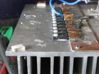
Anyone doing power measurements on a regular basis should build themselves a proper non-inductive reference load with surplus one sided pcb. This power "autobahn" in pic is built up from many 47R thick film resistors in parallel & can take 250W at 4 ohms.
Attachments
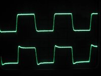
While on the topic of tube amp outputs; enclosed is a pic of two output signals feeding into a dummy load. I get asked this question so many times. Which one is the correct one ?
One shows near perfect square wave (correct one) as expected from a well designed tube amp, and the other with some HF advance suggesting the Zobels in the 1st stage or output global nfb isn't optimised..Generally alot of equipment shows part overshoot version. The reason is that alot of amateurs still use suplus metal mainframe oscilloscope equipment which has to be earthed. So as the main amp is also earthed in a nearby mains socket, by putting the earth probe on an output tranny return (also connected to chassis) one creates a signal circulation loop enough to upset the harmonic profile. (move probe lead around and see). The cure is to use a digital scope with completely isolated circuitry or disconnect either a mains earth or the scope probe earth.
Be aware of this ! Je higher the power amp, the more the problems !
Powering up the amp under test via an isolation tranny is another way of breaking the earth link.
 In any case, be aware of rising static chassis voltages that drift up posing as a shock hazard..I've seen it happen so many times with amps using input transformers.
richy
One shows near perfect square wave (correct one) as expected from a well designed tube amp, and the other with some HF advance suggesting the Zobels in the 1st stage or output global nfb isn't optimised..Generally alot of equipment shows part overshoot version. The reason is that alot of amateurs still use suplus metal mainframe oscilloscope equipment which has to be earthed. So as the main amp is also earthed in a nearby mains socket, by putting the earth probe on an output tranny return (also connected to chassis) one creates a signal circulation loop enough to upset the harmonic profile. (move probe lead around and see). The cure is to use a digital scope with completely isolated circuitry or disconnect either a mains earth or the scope probe earth.
Be aware of this ! Je higher the power amp, the more the problems !
Powering up the amp under test via an isolation tranny is another way of breaking the earth link.
In any case, be aware of rising static chassis voltages that drift up posing as a shock hazard..I've seen it happen so many times with amps using input transformers.richy
Attachments
I wanted to add, that the best way to make a high power dummy load is to submerge the resistor in a liquid for cooling.
I would buy a new empty 1 gallon paint can at your local hardware store. They cost about 1 to 2 dollars with a lid.
Install two insulated binding posts on the top. Drill the tinniest hole in the top of the can for pressure relief.
Solder your resistor or resistors together so they hang in the middle of the can when the lid is closed.
If you want to be fancy you can make a network of different impedances and just add more binding posts at the lid for versatility.
Fill the can 90% with mineral oil that you can buy at the local drugstore. The mineral oil will dissipate the heat from the resistor to prevent thermal destruction.
Radio Shack sells 8 Ω non-inductive resistors that work well for this.
HeathKit Cantenna!
Much the same, except a different impedance. I have built my share that way and they work great (if you don't spill the oil).
For those of us in the USA these are a nice choice.
8 Ohm 100W Non-Inductive Dummy Load Resistor
I have several and the 4 Ohm model as well. They also make a 200W.
Not the same as a real speaker load, but a consistent load. Watch out, they can get hot!
8 Ohm 100W Non-Inductive Dummy Load Resistor
I have several and the 4 Ohm model as well. They also make a 200W.
Not the same as a real speaker load, but a consistent load. Watch out, they can get hot!
I use a pair of these:
RESISTOR POWER ADJ 10 OHM 100W - D100K10RE
Since I adjust them to 8 ohms, they are derated to 80W each.
That encased one is probably a lot more durable, and easier to heat sink in additionto being cheaper.
RESISTOR POWER ADJ 10 OHM 100W - D100K10RE
Since I adjust them to 8 ohms, they are derated to 80W each.
That encased one is probably a lot more durable, and easier to heat sink in additionto being cheaper.
I wanted to add, that the best way to make a high power dummy load is to submerge the resistor in a liquid for cooling.
I would buy a new empty 1 gallon paint can at your local hardware store. They cost about 1 to 2 dollars with a lid.
Install two insulated binding posts on the top. Drill the tinniest hole in the top of the can for pressure relief.
Solder your resistor or resistors together so they hang in the middle of the can when the lid is closed.
If you want to be fancy you can make a network of different impedances and just add more binding posts at the lid for versatility.
Fill the can 90% with mineral oil that you can buy at the local drugstore. The mineral oil will dissipate the heat from the resistor to prevent thermal destruction.
Radio Shack sells 8 Ω non-inductive resistors that work well for this.
Hey, that's almost exactly what I was planning to do today! I went to Jaycar yesterday and got 8 x 68 ohm 10W resistors. I will be able to get an 8 ohm (or close enough) and 16 ohm test load - and that's fine at the moment as I only have these 8 and 16 ohm speakers. The power handling will be fine for my tube amps even without the oil but I will add it any way just to be sure.
Rob
- Status
- This old topic is closed. If you want to reopen this topic, contact a moderator using the "Report Post" button.
- Home
- Amplifiers
- Tubes / Valves
- Testing Amplifiers - Speaker or dummy load