It started during a time when they(JBL) searching for the optimal sound.
(That was Hartfield loudspeaker+ amp.)
Possibly the most under-appreciated product line ever introduced by JBL was their consumer electronics series from the 1960s. It was in every sense as groundbreaking as JBL’s most renowned loudspeakers, but due to marketing issues, would be short lived.
The consumer electronics line was the inspiration of Bill Thomas and Ray Pepe. They felt that JBL’s continued growth was dependent upon expanding beyond their traditional loudspeaker market to encompass electronics
as well. In the 1950s, JBL had established an informal association with McIntosh whereby each company had used the other’s products in demonstrations and promotional activities.
By 1960, that relationship was foundering as McIntosh sought to break the perception that their products were tied to any one loudspeaker company.
JBL thus felt free to compete with the likes of Fisher, Marantz, and, of course, McIntosh.
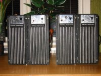
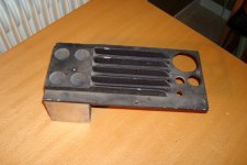
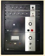
Pictured above is the first consumer electronics product attempted by JBL—the PL-100. A JBL engineer named Henry Wolcott developed a stereo pair of tube amplifiers that was solely intended to be integrated into the Hartsfield enclosure. They were unique in that they consisted of two amplifier sections and an electronic crossover sharing a common chassis. The amplifiers used
6973 output tubes to develop 40 watts for the low frequency section and 20 watts for the high-frequency section.
A number of prototypes were completed in 1960, but the amplifiers never went into production. The design would be very expensive to manufacture and the target market, restricted to Hartsfield owners, was considered
too small. There was also a technology issue. The transistor was becoming a viable replacement for output tubes in higher power applications and it was felt that the PL-100 would soon be made obsolete. For all of these reasons, management decided to cancel this product and begin development on a new amplifier that would have a broader market appeal.
The new amplifier was the model SE401.
(That was Hartfield loudspeaker+ amp.)
Possibly the most under-appreciated product line ever introduced by JBL was their consumer electronics series from the 1960s. It was in every sense as groundbreaking as JBL’s most renowned loudspeakers, but due to marketing issues, would be short lived.
The consumer electronics line was the inspiration of Bill Thomas and Ray Pepe. They felt that JBL’s continued growth was dependent upon expanding beyond their traditional loudspeaker market to encompass electronics
as well. In the 1950s, JBL had established an informal association with McIntosh whereby each company had used the other’s products in demonstrations and promotional activities.
By 1960, that relationship was foundering as McIntosh sought to break the perception that their products were tied to any one loudspeaker company.
JBL thus felt free to compete with the likes of Fisher, Marantz, and, of course, McIntosh.
Pictured above is the first consumer electronics product attempted by JBL—the PL-100. A JBL engineer named Henry Wolcott developed a stereo pair of tube amplifiers that was solely intended to be integrated into the Hartsfield enclosure. They were unique in that they consisted of two amplifier sections and an electronic crossover sharing a common chassis. The amplifiers used
6973 output tubes to develop 40 watts for the low frequency section and 20 watts for the high-frequency section.
A number of prototypes were completed in 1960, but the amplifiers never went into production. The design would be very expensive to manufacture and the target market, restricted to Hartsfield owners, was considered
too small. There was also a technology issue. The transistor was becoming a viable replacement for output tubes in higher power applications and it was felt that the PL-100 would soon be made obsolete. For all of these reasons, management decided to cancel this product and begin development on a new amplifier that would have a broader market appeal.
The new amplifier was the model SE401.
Attachments
There was a thread on the Wolcott amplifier and some related patents a while back:
http://www.diyaudio.com/forums/tubes-valves/58352-wollcott-cross-coupled-circuit.html
Any schematics available for any of these amplifiers? Would be interesting to trace the evolution of the designs up to the current sold "Presence 220". There appears to be some Wolcott laboratory amplifiers too, called Optimation PA-250H and PA-250AC.
The JBL PL-100 patent is H.Wolcotts not JBL:s. After this he started a company he continued develop amps but he went to bigger constructions
like PA-250, PA1015 etc.
Those was made mostly for calibration labs. like NIST
And he worked on the same topologie as the JBL PL-100 but used 8417 as output tubes
He used Negative and Positive FB in the amplifiers.
So I can adjust for best matching against the load and compenaste for wire Resitance.(DF)
Some of his amps:
1.JBL pl 100 balanced input with transformer (adjustable DF)
2. PA250 VT input (adjustable DF)
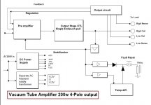
3. PA1015 with solid state input 2 transistors (adjustable DF) (se block schematic)
4. PA226 Single End Puss Pull ( with 4 wire connection) DC-100kHz
After this period he started the Wolcott audio with the Presence amplifier
Today H. Wolcott is not in buiseness but he have a partner who probebly can help owners of Wolcotts Amps.
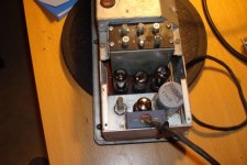
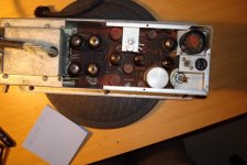
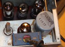
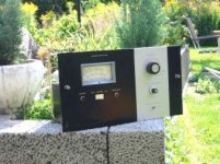
Pictures from left
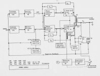
1.Cooler to PL-100 6973 tubes, 2. Input transformer + DF adj pot, 3. OT, 4. block schematic of wolcotts topologies
like PA-250, PA1015 etc.
Those was made mostly for calibration labs. like NIST
And he worked on the same topologie as the JBL PL-100 but used 8417 as output tubes
He used Negative and Positive FB in the amplifiers.
So I can adjust for best matching against the load and compenaste for wire Resitance.(DF)
Some of his amps:
1.JBL pl 100 balanced input with transformer (adjustable DF)
2. PA250 VT input (adjustable DF)
3. PA1015 with solid state input 2 transistors (adjustable DF) (se block schematic)
4. PA226 Single End Puss Pull ( with 4 wire connection) DC-100kHz
After this period he started the Wolcott audio with the Presence amplifier
Today H. Wolcott is not in buiseness but he have a partner who probebly can help owners of Wolcotts Amps.
Pictures from left
1.Cooler to PL-100 6973 tubes, 2. Input transformer + DF adj pot, 3. OT, 4. block schematic of wolcotts topologies
Attachments
The OT picture looks fairly thin, like it might be a toroid design?
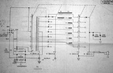
From the block diagram, it looks like a differential driver/splitter stage has positive feedbacks across it locally to increase gain. With both cathode followers and emitter followers lined up to drive it. I guess the input to the driver/splitter stage is coming through the cathodes like a Van Scoyoc splitter? Or possibly two White cathode followers? Wolcott's later(?) patents show additional nested feedback loops from the output stage plates too, I think.
From the block diagram, it looks like a differential driver/splitter stage has positive feedbacks across it locally to increase gain. With both cathode followers and emitter followers lined up to drive it. I guess the input to the driver/splitter stage is coming through the cathodes like a Van Scoyoc splitter? Or possibly two White cathode followers? Wolcott's later(?) patents show additional nested feedback loops from the output stage plates too, I think.
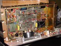
The Pa1015 looks like this and the main difference from Presence amplifier is the input stage ,WCF in presence and the output tubes. PA1015 have 8417 and Presence use EL34. And all stages is balanced beyond the first stage .
The first stage is a 7025 (with the FB in one half) then it drives a transistor pair to the 2 ECL86 then to 8 pcs 8417.
Wolcott designs works with both positive and negative FB.
The first stage is a 7025 (with the FB in one half) then it drives a transistor pair to the 2 ECL86 then to 8 pcs 8417.
Wolcott designs works with both positive and negative FB.
Attachments
Those Optimation amplifiers are something else. I happen to own several of them that I bought at the Government sales. (when you could do that before they ruined them in 2K) There was actually more then one version. The difference was in the output transformer secondary. Some had a higher voltage output with an H suffex on the model number. The lower voltage versions were pretty good for driving a speaker. Also, some of the output transformer cores were 100% interleaved and others were not. One of my projects was to make them into Hi-Fi amps, but I may never get to it. I've seen them with 8417s or EL34s for the outputs. And I remember that Julie Research Labs (Lobe Julie) bought out Optimation near the end. I have a manual with schematic for these but the diagram is a large foldout style blueprint. Very difficult to copy and impossible to post.
Perhaps you could scan just the section around the driver circuit? V90,V94 on attached diagram. I see where the PA1015 is part of an AC104A power AC source. Maybe OT interleaving was not required for limited freq. applications, ie. cost savings. Did these PA1015 OT have multiple output impedance taps? There seems to be a separate matching xfmr box T103 for the AC104A.
Attachments
It was very difficult to get information from him.
This is a the answer I got from Henry Wolcott about the differences .
The 8471 tubes are superior to the EL34 because they have a higher transconductance but have been obsolute for a long time. The later versions also tended to be gassy.The EL34 will work fine in the AC-104 but will require an increase in nominal grid bias voltage from minus 15 to about minus 33 volts.The input circuitry of the Ac 104 is different from the P220M in that it consists af a cathode follower,followed by a transistor emitter follower,whereas in P220-M uses a "White cathode follower" all tube circuit.
I would not replace the 12 AX7's.
----------------------------------
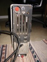
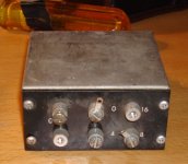
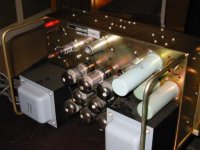
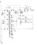
Left pic. Matching transformer for optimation AC104/PA1015 variable from 0,6 ohm to 6000hm in steps)
right pic. is output T2 from the amp.
This is a the answer I got from Henry Wolcott about the differences .
The 8471 tubes are superior to the EL34 because they have a higher transconductance but have been obsolute for a long time. The later versions also tended to be gassy.The EL34 will work fine in the AC-104 but will require an increase in nominal grid bias voltage from minus 15 to about minus 33 volts.The input circuitry of the Ac 104 is different from the P220M in that it consists af a cathode follower,followed by a transistor emitter follower,whereas in P220-M uses a "White cathode follower" all tube circuit.
I would not replace the 12 AX7's.
----------------------------------
Left pic. Matching transformer for optimation AC104/PA1015 variable from 0,6 ohm to 6000hm in steps)
right pic. is output T2 from the amp.
Attachments
- Status
- This old topic is closed. If you want to reopen this topic, contact a moderator using the "Report Post" button.
- Home
- Amplifiers
- Tubes / Valves
- JBL Amplifier story