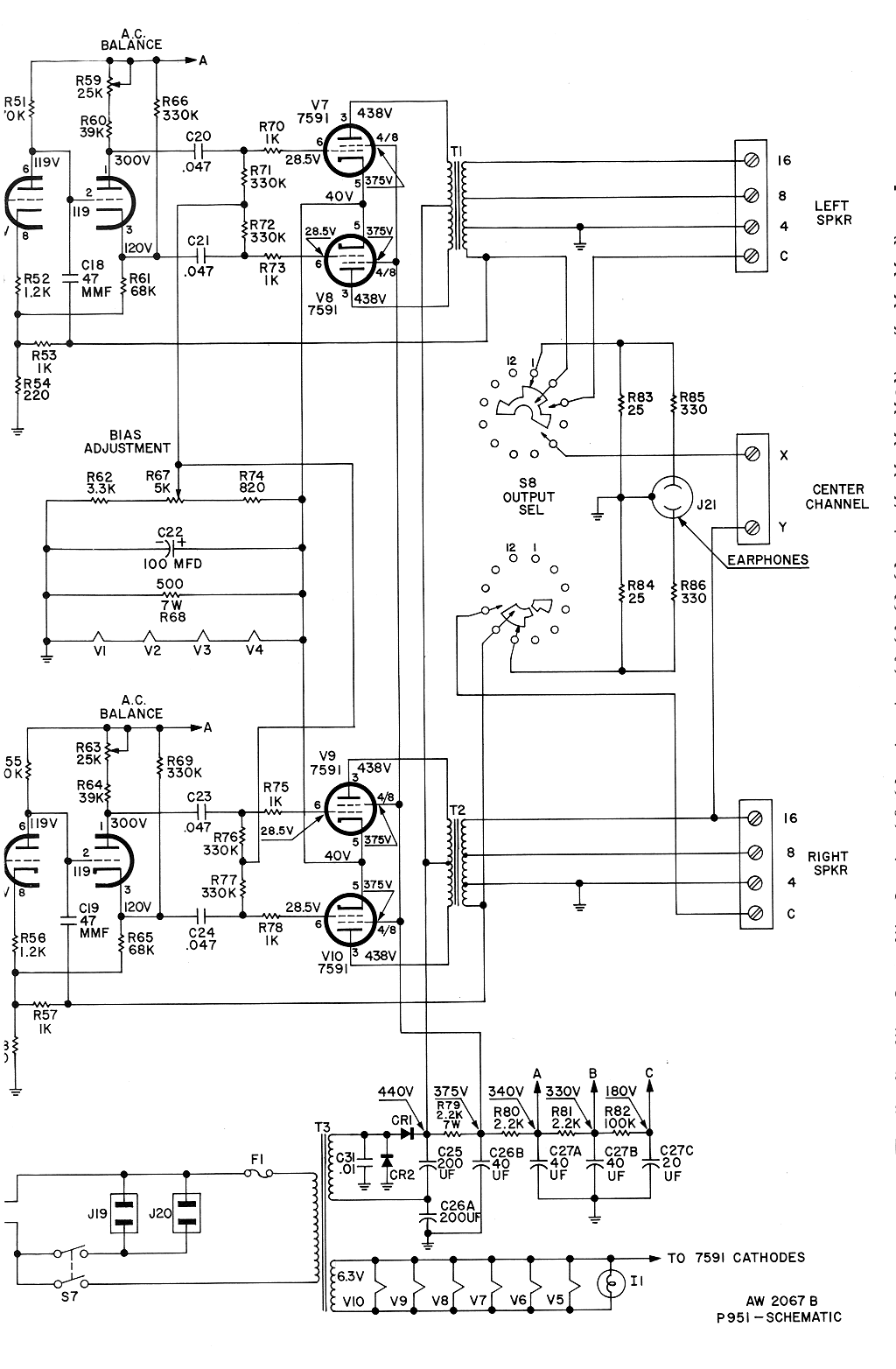
I have a Fisher X-101-C that I picked up in nonworking condition and it's up and running now but the bias circuit seams a bit bizzare to me and I need a little help understanding it.
The schematic:

The diagram calls for a 438V plate, a 375V G2 a 40V cathode and a 28.5V grid. Bias then is -11.5V.
The cathode current makes it's way to ground in two ways: across the 500 ohm resistor and across the series filaments of the four 12AX7s. Lets say 80ma in the resistor and perhaps another 120 through the series filaments (operating at 10V each). A total of 200ma or 50ma per tube. It works out to about 20 watts, I think.
The thing that bugs me is that the 11.5V bias won't get us anywhere near 50ma current. It looks closer to 90ma on the Sylvania drawings and it measures at just above 90ma too. Am I missing something here. It seems way to high (35 watts).
And, does the 20watt plate dissipation sound about right? I'm having difficulty determining the max value at this operating point. I'd like to operate these tubes at a conservative 70% of max disipation. What would you think would be the correct operating point. I'd think about 18 watts.
Any help here would be appreciated.
Sylvania 7591A data
The schematic:

The diagram calls for a 438V plate, a 375V G2 a 40V cathode and a 28.5V grid. Bias then is -11.5V.
The cathode current makes it's way to ground in two ways: across the 500 ohm resistor and across the series filaments of the four 12AX7s. Lets say 80ma in the resistor and perhaps another 120 through the series filaments (operating at 10V each). A total of 200ma or 50ma per tube. It works out to about 20 watts, I think.
The thing that bugs me is that the 11.5V bias won't get us anywhere near 50ma current. It looks closer to 90ma on the Sylvania drawings and it measures at just above 90ma too. Am I missing something here. It seems way to high (35 watts).
And, does the 20watt plate dissipation sound about right? I'm having difficulty determining the max value at this operating point. I'd like to operate these tubes at a conservative 70% of max disipation. What would you think would be the correct operating point. I'd think about 18 watts.
Any help here would be appreciated.
Sylvania 7591A data
Last edited:
I think whats throwin you off is the resistance in the cathode which will limit dissipation.The resistance and the tubes form a voltage divider that reduces the effective plate voltage from the 438 that is there then subtracting the 40 at the cathode results in 398 volts across the tubes.at a listed 85ma for two plates and adding another 11ma for screen draw,it doesn't appear that there is anything wrong.The 19.9 watss dissipation is right at the edge but then again it probably sounds really good!If anything I would maybe reduce the screen voltage to back it down a little.But you may not like the sound.And reducing the draw may drop the 12AX7 heaters too low. But you can try it.
Yeah, that and the fact that I still struggle with the plate and transfer characteristic charts. These charts are for a single tube, right?
Everything thing you say is correct but I'm still high centered on the bias voltage issue. Note that the drawing shows a -11.5v bias. The second plate characteristic chart would seem to be the applicable one. 400v max plate dissipation is about -14v. Operation at 11.5 is nearly double that max figure, correct? I don't believe for a minute that Fisher fouled up the design, but I can see where my thinking leave the tracks. What am I missing?
I like your 85ma and 11ma numbers. Lets say 96 for a pair and 48ma for one. The transfer characteristics chart shows about 92ma at -11.5 and about 63ma at -14v. Both of these figures seem higher than the max dissipation. What can be gleaned form that?
Thanks for responding, I appreciate the help.
Dave
- Status
- This old topic is closed. If you want to reopen this topic, contact a moderator using the "Report Post" button.