Good day Gents,
This is my first post here so bear with me. I'm a complete beginner when it comes to electronics but i have the motto that you have to try to learn something.
Either way my current learning project is an Aikido pre-amp based on an all-in-one octal kit. Everything is assembled and working fine when not using a volume potentiometer.
I have looked everywhere on how to actually connect those things to not create ground-loops, but i seem to have failed quite drastically there")
I have used my non-existing image editing skills to create a sort of overview of how all inputs and outputs are connected which can be seen in the image below ->
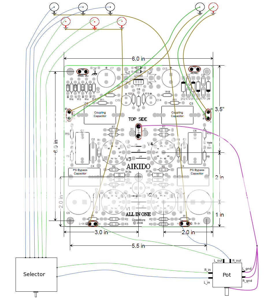
The input connectors are to the top left, and all hot signals goes to the signal selector and then continue to the pot. The grounds of the inputs are connected channelwise and then connected to the input grounds on the PCB.
The signal output from the potentiometer are connected to the signal inputs on the PCB. The ground from the pot are connected together (the left&right and the pot housing ground) and then directly to the main G in the center of the PCB. I guess that this approach is quite wrong but i'm unsure how it actually works. The ground from the pot, isn't that just something that needs to be "dumped" out somewhere?
The safety ground (third prong) is connected via a set of diodes (image below) to J7 (to the upper left of the pcb in the picture above), and the pcb is then connected to the top metal chassis trough with a screw.
Does anyone have any tips here on what i'm doing wrong, bring out the teacher within and give me the lecture of a lifetime!
Thanks for taking the time.
Andreas
This is my first post here so bear with me. I'm a complete beginner when it comes to electronics but i have the motto that you have to try to learn something.
Either way my current learning project is an Aikido pre-amp based on an all-in-one octal kit. Everything is assembled and working fine when not using a volume potentiometer.
I have looked everywhere on how to actually connect those things to not create ground-loops, but i seem to have failed quite drastically there
I have used my non-existing image editing skills to create a sort of overview of how all inputs and outputs are connected which can be seen in the image below ->
The input connectors are to the top left, and all hot signals goes to the signal selector and then continue to the pot. The grounds of the inputs are connected channelwise and then connected to the input grounds on the PCB.
The signal output from the potentiometer are connected to the signal inputs on the PCB. The ground from the pot are connected together (the left&right and the pot housing ground) and then directly to the main G in the center of the PCB. I guess that this approach is quite wrong but i'm unsure how it actually works. The ground from the pot, isn't that just something that needs to be "dumped" out somewhere?
The safety ground (third prong) is connected via a set of diodes (image below) to J7 (to the upper left of the pcb in the picture above), and the pcb is then connected to the top metal chassis trough with a screw.
An externally hosted image should be here but it was not working when we last tested it.
Does anyone have any tips here on what i'm doing wrong, bring out the teacher within and give me the lecture of a lifetime!
Thanks for taking the time.
Andreas
Hi Sy, thanks for your response. I apologize for being a bit slow but i'll try to explain how i understood your comment.
Instead of connecting the safety ground through the diodes to the pcb (which is connected to the chassis) i should isolate the pcb from the chassis and connect safety ground directly to the chassis and then from that connection point go through diodes to connect to the pcb "earth"?
The input and output connectors are isolated from the chassis.
So you believe that the issue with audible hum (which gets louder with increasing the volume knob) comes from the safety earth being connected in a bad way (with the diodes).
Maybe it could help if i used a photo to illustrate how things are connected ?
Many thanks!
/Andreas
Good morning,
I was having a short 'meditation session' during breakfast about the grounding issue and decided i would do yet another sketch
Maybe if someone could just give an indication that the ground part of the volume pot is ok then i can focus on the safety ground as this might be the root cause for the hum that i have in my setup.
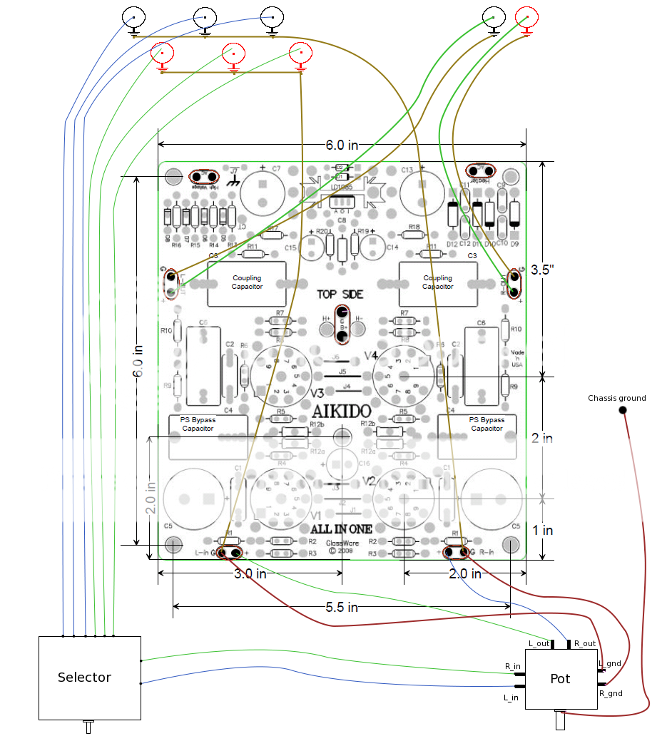
Based on Sy's comment yesterday i thought about how to connect the safety ground. Would it be ok to do as i've done in the image below ?
To go from the third prong directly to a bolt in the chassis top (aluminum, rest of chassis is wood) and then from that bolt go through the diodes and to the J7 jumper on the board.
With this approach i guess that i should use the rubber o-rings so that the only connection to the chassis is done at the bolt and not through the top-left mounting hole (which is what i am doing at the moment)
Any input would be dearly appreciated.
/Andreas
I was having a short 'meditation session' during breakfast about the grounding issue and decided i would do yet another sketch
Maybe if someone could just give an indication that the ground part of the volume pot is ok then i can focus on the safety ground as this might be the root cause for the hum that i have in my setup.
Based on Sy's comment yesterday i thought about how to connect the safety ground. Would it be ok to do as i've done in the image below ?
An externally hosted image should be here but it was not working when we last tested it.
To go from the third prong directly to a bolt in the chassis top (aluminum, rest of chassis is wood) and then from that bolt go through the diodes and to the J7 jumper on the board.
With this approach i guess that i should use the rubber o-rings so that the only connection to the chassis is done at the bolt and not through the top-left mounting hole (which is what i am doing at the moment)
Any input would be dearly appreciated.
/Andreas
That diagram looks better. The idea of the safety ground is to have EVERY exposed metal part be connected to a place that has zero potential with respect to the ground that we stand on. So if the third wire is not connected directly and firmly to the chassis, there's a danger that this connection will be broken, causing a shock hazard.
With that disposed of, now we need to look at the circuitry. The "ground" in that context is a different animal, but confusingly has the same name. In this context, it's a common reference point for all of the signals. So that's why one isolates the jacks from the chassis and returns their signal grounds to the single point signal ground reference (probably on the board, if it's well-designed, which I'm sure Broskie's is).
OK, so now we have two different "grounds." One is the signal ground, one is the safety ground. Many times, these can be connected directly together. Sometimes, though, this will cause a hum when interacting with the grounding in other components. One way around that is a "ground lift," where the connection between the two "grounds" is removed. This also can present some safety issues, so as an expedient, the back-to-back diode method is often used. Another common method is a small value resistor (10-50 ohms), but there are some safety concerns there that the resistor could go open in the event of a power fault- diodes tend to fail short-circuit, which will cause a breaker to trip or fuse to blow if there's a power fault. Clearly that's better than electrocuting the user (well, depending on the user; I have a little list...). Really, all you need is a single diode in each direction, not two in series, though.
Hope this clarifies things a bit. Dave Davenport wrote an excellent article on grounding which should be appearing shortly. And this gives me the second opportunity today to gripe about the ambiguity of the word "ground."
That diagram looks better. The idea of the safety ground is to have EVERY exposed metal part be connected to a place that has zero potential with respect to the ground that we stand on. So if the third wire is not connected directly and firmly to the chassis, there's a danger that this connection will be broken, causing a shock hazard.
With that disposed of, now we need to look at the circuitry. The "ground" in that context is a different animal, but confusingly has the same name. In this context, it's a common reference point for all of the signals. So that's why one isolates the jacks from the chassis and returns their signal grounds to the single point signal ground reference (probably on the board, if it's well-designed, which I'm sure Broskie's is).
OK, so now we have two different "grounds." One is the signal ground, one is the safety ground. Many times, these can be connected directly together. Sometimes, though, this will cause a hum when interacting with the grounding in other components. One way around that is a "ground lift," where the connection between the two "grounds" is removed. This also can present some safety issues, so as an expedient, the back-to-back diode method is often used. Another common method is a small value resistor (10-50 ohms), but there are some safety concerns there that the resistor could go open in the event of a power fault- diodes tend to fail short-circuit, which will cause a breaker to trip or fuse to blow if there's a power fault. Clearly that's better than electrocuting the user (well, depending on the user; I have a little list...). Really, all you need is a single diode in each direction, not two in series, though.
Hope this clarifies things a bit. Dave Davenport wrote an excellent article on grounding which should be appearing shortly. And this gives me the second opportunity today to gripe about the ambiguity of the word "ground."
Building on that, what you should do is to return each pot ground lug (which actually is the 'reference' for the signal) to the pcb pad where you also returned the input screens.
The best way, if you use a screened cable to get the signal from the selector to the pot and then onwards to the input on the pcb, is to picture the pot as a component halfway a screened cable from selector to pcb. The pot ground lug, in that picture, connects to the screen, the hot from selector to pot top, the hot from pot wiper to input on pcb, together with the screen.
I'll bet now your hum is gone.
jd
If the hum gets louder with increasing volume knob position, wouldn't that make the issue 'upstream' of the volume knob?
You say that your RCA inputs and outputs are isolated from the chassis, make sure that your volume pot and input selector are as well.
These things can be a pain to chase, but you usually learn a few lessons on the way!
Good luck,
Chris
You say that your RCA inputs and outputs are isolated from the chassis, make sure that your volume pot and input selector are as well.
These things can be a pain to chase, but you usually learn a few lessons on the way!
Good luck,
Chris
Ah, yes, Janneman makes a good point...
Looks like you have put the audio signal ground reference (from the volume pot) to the ground reference of the power supply (the pad next to where you have connected the input signal ground is B+, the nomenclature for power supply positive voltage). Connect the ground reference from the pot to the ground reference pad next to the signal wiring input as mentioned by janneman. Make the power supply ground connection at that ground point in the middle of the PCB.
Hope that fixes it,
Chris
Wow guys, you are overflooding me with lots of good information here that i am currently digesting (together with the pasta i had for lunch).
I DO see this project as a learning project and i'm not in any rush of getting to that "good enough" state but all these tips makes me want to go home from work early and put my hands on the preamp
I will do what SY mentions and change the way the safety ground is connected to the chassis just to cover the safety aspect (as i'm too young to die).
And just to quickly answer chrish's first post all the inputs/outputs and selector&pots are isolated from the chassis.
So just a clarification from my side here, the pot ground lugs should go to the signal input ground on the pcb together with the input connector grounds? Just thinking about this graphically wouldn't "that" created a loop? (this is the reason why i connected the pot ground lugs to the B+ ground as i thought the ground lugs from the pot was like a "trash bin" that should be disposed of somewhere)
Many many thanks, and i'll look forward taking these good pointers with me back home
/Andreas
Wow guys, you are overflooding me with lots of good information here that i am currently digesting (together with the pasta i had for lunch).
I DO see this project as a learning project and i'm not in any rush of getting to that "good enough" state but all these tips makes me want to go home from work early and put my hands on the preamp
I will do what SY mentions and change the way the safety ground is connected to the chassis just to cover the safety aspect (as i'm too young to die).
And just to quickly answer chrish's first post all the inputs/outputs and selector&pots are isolated from the chassis.
So just a clarification from my side here, the pot ground lugs should go to the signal input ground on the pcb together with the input connector grounds? Just thinking about this graphically wouldn't "that" created a loop? (this is the reason why i connected the pot ground lugs to the B+ ground as i thought the ground lugs from the pot was like a "trash bin" that should be disposed of somewhere)
Many many thanks, and i'll look forward taking these good pointers with me back home
/Andreas
Andreas, just to be sure: my term 'pot ground lug' referred to the bottom pin of the resistive element, NOT the housing of the pot. My term is admittedly not very accurate, sorry about that. The pot housing is connected to the chassis presumably.
In principle you are correct that there is a ground loop as the screens of the cables that bring in the signal eventually end up on the same potential, signal ground on the pcb. If they are also connected that way at the source, there is a loop.
The saving grace is 1) keep the screened signal cables close together to minimize the loop, and 2) by not connecting them at more than one place to safety ground, you also limit hum and noise injection.
It IS possible that you still get hum. In that case, just disconnect the connection of the screen of ONE channel only at the pcb input pad.
have fun!
jd
Great information Janneman, i'll make sure that the pot housing goes to chassis and the ground pins on the pot to the input signal ground on the pcb together with the input connector grounds. The hot cables from the rca inputs are unshielded and i only 1 cable of each 'pair' is connected (the story behind this is that when i has the input rca ground to the selector switch i got quite an unpleasant 'thump' when switching input, so instead i connected all the input connector grounds together (per channel) and directly to the pcb.
So there is no screen connected at all which probably isn't optimal but i didn't have any audible noise when connecting with the same cables and omitting the volume pot.
So indeed i have some new things to try out and the working day is slowly but surely going towards its end
Thanks! Dank u wel!
So there is no screen connected at all which probably isn't optimal but i didn't have any audible noise when connecting with the same cables and omitting the volume pot.
So indeed i have some new things to try out and the working day is slowly but surely going towards its end
Thanks! Dank u wel!
As i couldn't find a smart way to edit my last post i'll add a follow-up here. I tried once again to use my wonderful sketching skills to show how i assume that i should connect the ground lugs from the volume pot.
Is it a correct assumption?
Compare that to the first sketch i posted.
Many thanks!
Andreas
Is it a correct assumption?
Compare that to the first sketch i posted.
Many thanks!
Andreas
Hello Andres
Well not quite everywhere. Rather than to answer your questions, I suggest that you read my article on grounding and interconnection first and then once you have the basic concepts I'll be glad to help you with the details.
http://www.raleighaudio.com/Audio Component Grounding and Interconnection.pdf
Dave
I have looked everywhere on how to actually connect those things to not create ground-loops, but i seem to have failed quite drastically there
Well not quite everywhere.
Rather than to answer your questions, I suggest that you read my article on grounding and interconnection first and then once you have the basic concepts I'll be glad to help you with the details. http://www.raleighaudio.com/Audio Component Grounding and Interconnection.pdf
Dave
Whoah, that seems to be a very informative document written in a way that is understandable even for a beginner like me. I will take a pause from the experiments on the amplifier until i've finished reading it and trying to understand most.
The latest status now before i go into "reading-mode" is that i conneted the ground lugs to the positions indicated previously, and the result is the same. With one hand behind the back i tried to see if the sound becomes worse if moving some cables
, and once my hand is getting close the the signal out from the pot the humming become ALOT stronger. Which i assume is that the grounding from the pot is wrong, but i'll read the documentations and see it touches those symptoms at all.
Cheerio!
So what fixed the problem in the end?
It's a bit embarrasing but it was actually quite many different things that i think contributed. To start with i found that my rca jacks wasn't isolated from chassis, so that was fixed, but the main changes was to redo my signal and ground cables, using shielded ones and keeping them as far away from any power cables.
I also installed a ground lifter between earth and pcb ground.
As i didn't try it out between the different iterations i can't really point on anything specific, but it has reached a level that i am satisfied with, i can't hear it from my listening position.
Hello Andres
Well not quite everywhere.
http://www.raleighaudio.com/Audio Component Grounding and Interconnection.pdf
Dave
Hi Dave and all,
Well I have the same issue as the OP with a Chinese tube amp. The amp dropped a channel so I took it off to a tech to have it looked at (should have done it myself but it was 2 weeks old) anywho - I read a good deal of your article you pointed to.
Backround: Amp is a Yaqin MC-100B - it has direct inputs on the front and also tuner, CD, Aux, tape inputs on the back. The only difference in the circuit between the direct input @ 600mV and the "preamp" inputs 250mV is a pair of resistors lowering the impedance for consumer gear not going thru a preamp AND and input selector switch. The cables from the inputs on the back go directly to the input selector switch.
After getting the amp "serviced", the tech say there was a wire that was not connected to anything up near the input selector switch which he soldered down. Result was a drastic hum that got louder as I turned up the volume and also very bad distortion/low output.
Well after reading some of you paper I realized that if I plugged in a box that converts un-balanced cable to balanced cable and it does the reverse as well it might get rid of the hum. So I plugged in the box (Aphex 124a) into another one of the inputs on the back and low and behold the hum is gone. If I unplug the Aphex box the hum is back.
I'm thinking the ground wire the tech soldered down was put in the wrong location. Now I have to open up the unit and find the ground wire - probably the ground for the selector switch and re-solder it in another (proper) location.
Dave feel free to comment if you read an AH-HA thing that jumps out from what I've listed above and guide me.
Cheers and Hi to all I'm new here,
Bob
Hi Bob,
I got to shake my head and wonder how the tech decided where to solder the wire.
You might consider a couple of things: First placing a specific post for that amplifier on the forum to see if you can find someone who owns one and will open it up to see where the wire is supposed to go. And if that fails, you could contact the manufacturer and ask them.
Dave
- Status
- This old topic is closed. If you want to reopen this topic, contact a moderator using the "Report Post" button.
- Home
- Amplifiers
- Tubes / Valves
- YAAGLI - Yet Another Aikido Ground Loop Issue