Have switched out the output stage bridge rectifiers for Hexfreds, but still have got some buzzing / sizzling through the speakers so am going to have to investigate a little further and look at trying some snubbers. Fortunately it's not too obtrusive once the music is playing, so am not overly concerned at this stage.
They now have around 50 hrs on them and sound quality has improved significantly. They are now very listenable, and still improving. Midrange and treble are excellent. Bass is a little soft at the moment. I'm a huge fan of the prog rock band Yes, and Chris Squire's bass just doesn't quite have the growl it should have. Hopefully this will improve as more hours are put on the amps. I know Ralph has specific views on output impedances, but I do wonder if the high output impedance of the amps is contributing to this issue. I suppose that the zero autoformers are an option, but it just seems extremely illogical to me to build a superb OTL amp and then stick a transformer between it and the speakers.
I would be interested to hear other peoples views on this.
Overall, I'm extremely pleased with the amps. A few teething issues to resolve, but that's one of the challenges of DIY stuff. Thanks again to Ralph for making the schematic available to the DIY community
Cheers,
Steve.
What are your loudspeakers? I'm an old school Yes fan myself...
Thanks Demonkleaner. Have dome the mods with mixed results, and things unfortunately are getting worse rather then better.
Measuring the voltages at the cathodes of V3 and V4, I get -90V at the cathode of V3A (from V1), -210V at the cathode of V3B and -70V at the cathodes of V4
The heaters for V1 and V2 are in parallel off one winding of the transformer and have been tied to ground, using 2, 220 ohm resistors across the heaters to effectively create a centre tap for the transformer winding. The earth connection is connected between the two resistors.
The heaters for V3 and V4 are also in parallel off a second winding, and again through 2 220 ohm resistors. These have been tied to a voltage divider off B-(2) at -140V. This puts all 4 6SN7's within the +/-100V limit between heaters and cathodes.
Whilst this has reduced the buzzing slightly, I now have a lot of spitting and popping from the amp. More worryingly, it now squeals when turned off.
The spitting and popping is similar to a problem I had with a Transcendent Sound phono stage, and this was cured by putting a 1k resistor in series at the input socket. Tried the same thing here. No change.
But here is the real clue (potentially) to the problem.
I have a fairly long run of cable from the input socket to V1, around 300mm (or 12 inches for you guys across the pond) due to the layout of the chassis. I'm just using a phono socket, not running balanced with an XLR). This is done with a twisted pair of wires, soldered from the input socket to 2 solder lugs just above V1. The 4.75k resistor is then soldered between the solder lug and the tube socket. The 100k grid leak is connected from the tube socket to the star ground.
I have an earth wire running from the star ground to the solder lug where the earth wire from the input socket is soldered. Now here's the interesting bit. If I remove the earth wire from the solder lug and solder it directly to the input socket, the spitting and popping gets significantly worse. DC wise, the circuit is identical, as all I am doing is moving an earth wire from one end of another piece of wire to the other, but this now has oscillation written all over it.
So if anyone has any suggestions as to where to start sorting this out, I would be extremely grateful.
Cheers,
Steve.
If you are using a separate transformer for the filament of the voltage amplifier, one thing you have to watch for is electrostatic leakage from the AC line!
After a bunch of hokey bandaids we just ran the filaments off of the filament supply for the output tubes and that sorted that problem...
Progress at last
Hi All,
It's been a productive day. It's a public holiday here in the UK so have had some time to try and get my head round the problems with the amps.
Decided to go old school, throw the schematic away and just apply some basic good tube amp practice, and I'm pleased to say it seems to have worked. Still got a bit of buzz, which could be electrostatic leakage as Ralph has suggested, as I am using the 6V windings on the Antek transformer that is powering the voltage amp, but apart from that, no popping, no squealing, no hum and a beautiful clear sound, which is a huge step up from where we were 24 hrs ago. So what has been done -
Have added 1k grid stoppers to V2 and V4
The 100k resistor between the grids of V3 has been soldered directly to the socket pins and the wiring tidied up.
All heaters have been tied to earth, except the heaters for V3 and V4 which have been tied to a voltage divider at -140V to ensure we don't exceed the heater cathode voltage limits.
The twisted pair of wires from the input socket to V1 have been replaced with a piece of coax cable.
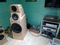
The speakers are basically Troels Gravesen's OBL15's, built into a modular setup which allows me to experiment. (See photo below) Instead of a large wide baffle, I turned it into boxes without backs on them and each driver is in its own enclosure. I'm sure that Troels would be throwing up his hands in horror as I've probably messed up all the diffraction adjustments that are built into the crossover, but they still sound absolutely superb. The midrange driver is a high efficiency one that Troels developed himself and is made for him by Seas. There are two tweeter options available for the speakers, and I'm currently using the basic Audax unit. You can fit a Seas tweeter without any changes to the crossover, but this is around 3 times the price, so will have to wait. The bass driver is a 15 inch unit which is the same as in the Humble Homemade HiFi Calpamos. I also have the horn treble unit (Faital Pro HF201) from the Calpamos that I can switch over with it's own crossover, so can quite easily switch between the two speaker systems.
It's been quite interesting listening to the two speaker options. Whist I have been building the M-60's, I've been using an old Krell KSA50. With that power amp, the Calpamos was the clear winner, producing a clear open and dynamic sound. With the M-60's, the sound is much more open, to the point where the horns were starting to get a bit shouty and overpowering, whereas the OBL15's have opened up to give a very neutral presentation, but still with the dynamics that the horns had with the KSA50. So I suspect the OBL15's will be staying in the system for some time to come.
Having the Krell, does, of course, open up another interesting possibility of biamping the system, using the M-60's for the mid and treble drivers and the Krell for the bass. Definitely one to try.
One final question, Ralph.
You mention that you got rid of the electrostatic leakage problem by using the output stage filament supply for the voltage amplifier. How did you deal with the heater / cathode voltage issues with V3 and V4, or didn't you worry about it.
Cheers,
Steve.
Hi All,
It's been a productive day. It's a public holiday here in the UK so have had some time to try and get my head round the problems with the amps.
Decided to go old school, throw the schematic away and just apply some basic good tube amp practice, and I'm pleased to say it seems to have worked. Still got a bit of buzz, which could be electrostatic leakage as Ralph has suggested, as I am using the 6V windings on the Antek transformer that is powering the voltage amp, but apart from that, no popping, no squealing, no hum and a beautiful clear sound, which is a huge step up from where we were 24 hrs ago. So what has been done -
Have added 1k grid stoppers to V2 and V4
The 100k resistor between the grids of V3 has been soldered directly to the socket pins and the wiring tidied up.
All heaters have been tied to earth, except the heaters for V3 and V4 which have been tied to a voltage divider at -140V to ensure we don't exceed the heater cathode voltage limits.
The twisted pair of wires from the input socket to V1 have been replaced with a piece of coax cable.
What are your loudspeakers? I'm an old school Yes fan myself...
The speakers are basically Troels Gravesen's OBL15's, built into a modular setup which allows me to experiment. (See photo below) Instead of a large wide baffle, I turned it into boxes without backs on them and each driver is in its own enclosure. I'm sure that Troels would be throwing up his hands in horror as I've probably messed up all the diffraction adjustments that are built into the crossover, but they still sound absolutely superb. The midrange driver is a high efficiency one that Troels developed himself and is made for him by Seas. There are two tweeter options available for the speakers, and I'm currently using the basic Audax unit. You can fit a Seas tweeter without any changes to the crossover, but this is around 3 times the price, so will have to wait. The bass driver is a 15 inch unit which is the same as in the Humble Homemade HiFi Calpamos. I also have the horn treble unit (Faital Pro HF201) from the Calpamos that I can switch over with it's own crossover, so can quite easily switch between the two speaker systems.
It's been quite interesting listening to the two speaker options. Whist I have been building the M-60's, I've been using an old Krell KSA50. With that power amp, the Calpamos was the clear winner, producing a clear open and dynamic sound. With the M-60's, the sound is much more open, to the point where the horns were starting to get a bit shouty and overpowering, whereas the OBL15's have opened up to give a very neutral presentation, but still with the dynamics that the horns had with the KSA50. So I suspect the OBL15's will be staying in the system for some time to come.
Having the Krell, does, of course, open up another interesting possibility of biamping the system, using the M-60's for the mid and treble drivers and the Krell for the bass. Definitely one to try.
One final question, Ralph.
You mention that you got rid of the electrostatic leakage problem by using the output stage filament supply for the voltage amplifier. How did you deal with the heater / cathode voltage issues with V3 and V4, or didn't you worry about it.
Cheers,
Steve.
Attachments
6SN7s don't seem to careYou mention that you got rid of the electrostatic leakage problem by using the output stage filament supply for the voltage amplifier. How did you deal with the heater / cathode voltage issues with V3 and V4, or didn't you worry about it.
Cheers,
Steve.
")
Regarding your speakers, in the photo I see another woofer off to the side. If that speaker isn't being used, place a short across its speaker terminals to keep it from absorbing bass.
The sound of silence
Thanks Ralph, I'll give it a go with a shorting plug across the terminals.
On even better news, have now finally got rid of all the buzz and hum, to the point where you cannot tell if the amps are on or not, they are that quiet. In the end it was a simple fix, just moving a few earth wires around to create an earth node for the voltage amp and then feeding that back to the main star earth. That being said, I'm sure some of the other work in fitting the grid stoppers and earthing the heaters all contributed to the final result.
This just now leaves one final problem, they are now that quiet that they are no longer masking the hum / hiss from upstream, so a little more work is required in that department, unless I can finish off the MP-3 schematic in the other thread of course.
Thanks to everyone for their input in getting the amps to this point, especially Ralph, and Demonkleaner for suggesting some of the points to check on resolving the instability / buzz issues. It's been a great learning curve, so will have a bit of a break, enjoy listening to my record / CD collection, and contemplate the next step on this highly enjoyable (well at least most of the time) hobby
Cheers,
Steve.
Thanks Ralph, I'll give it a go with a shorting plug across the terminals.
On even better news, have now finally got rid of all the buzz and hum, to the point where you cannot tell if the amps are on or not, they are that quiet. In the end it was a simple fix, just moving a few earth wires around to create an earth node for the voltage amp and then feeding that back to the main star earth. That being said, I'm sure some of the other work in fitting the grid stoppers and earthing the heaters all contributed to the final result.
This just now leaves one final problem, they are now that quiet that they are no longer masking the hum / hiss from upstream, so a little more work is required in that department, unless I can finish off the MP-3 schematic in the other thread of course.
Thanks to everyone for their input in getting the amps to this point, especially Ralph, and Demonkleaner for suggesting some of the points to check on resolving the instability / buzz issues. It's been a great learning curve, so will have a bit of a break, enjoy listening to my record / CD collection, and contemplate the next step on this highly enjoyable (well at least most of the time
) hobbyCheers,
Steve.
One quick question for Ralph,
The spec on your website for the M-60's states the gain of the amp at 20dB
Am I right in assuming that this is in balanced mode, and for a single ended input we will be down by 6dB.
The reason I ask is that I am currently running in single ended mode, and the gain is significantly lower than with the Krell which is spec'd at 26dB.
It isn't a problem as I am just using more of the volume control travel, but will be useful to know if and when I try bi-amping with the M-60's and the Krell so I can get the output levels right with both amps.
Thanks
Steve.
Thanks Ralph,
No my preamp(s) certainly don't support AES48 so I'll be running single ended for a while, until such time as the forum community have helped in developing the MP-3 clone we are discussing in another thread or I end up building something else.
I currently have 3 preamps available to use, and have been trying all 3 with the M-60's with some interesting results
Two are Transcendent units, the Grounded Grid and the Masterpiece, and I also have an old chinese clone thing (Lite Audio LS26, IIRC) supposedly based on the CAT SL1. The chinese clones generally get a slating in this forum, but it's a classic case of don't knock it till you've tried it. They have reverse engineered the basic audio circuitry and added a simple power supply, and there you go, you suddenly have $15,000 worth of pre-amp. It would be laughable if it wasn't for the fact that once you've rectified a few mistakes that all of these clones have, the results are actually very good indeed. I've currently got it in the system feeding the M-60's and have just been listening to Stevie Ray Vaughan playing Tin Pan Alley at rather loud levels. It's a very well recorded track and one I use regularly for evaluation. The dynamics with this setup are absolutely stunning.
The grounded grid does a reasonable job too, and I'm hoping for great things with the Masterpiece but it has just sh*t itself and is currently out of commission with a faulty 300B socket
So that leads me nicely back onto suitable balanced pre-amps for use with the M-60's
The thread where we have been discussing the MP-3 seems to have fizzled out, so looks like I'm on my own now and unfortunately I don't have the skills to finish off the schematic to a point where it is going to be workable, so I am currently looking at alternatives. I appreciate that we are getting a little off topic here, so apologies for that.
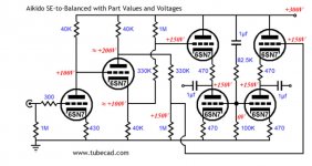
John Broskie has an interesting circuit on his tubecad website, which according to the text is near enough ready to go, and I was wondering if anyone had any thoughts on it and whether it would be a good match for the M-60's. (Schematic below). I appreciate this is taking us away from Atma-Sphere products, so if Ralph prefers not to comment then I fully understand. It should be fairly simple to build point to point, so I might have a go anyway.
Cheers,
Steve.
No my preamp(s) certainly don't support AES48 so I'll be running single ended for a while, until such time as the forum community have helped in developing the MP-3 clone we are discussing in another thread or I end up building something else.
I currently have 3 preamps available to use, and have been trying all 3 with the M-60's with some interesting results
Two are Transcendent units, the Grounded Grid and the Masterpiece, and I also have an old chinese clone thing (Lite Audio LS26, IIRC) supposedly based on the CAT SL1. The chinese clones generally get a slating in this forum, but it's a classic case of don't knock it till you've tried it. They have reverse engineered the basic audio circuitry and added a simple power supply, and there you go, you suddenly have $15,000 worth of pre-amp. It would be laughable if it wasn't for the fact that once you've rectified a few mistakes that all of these clones have, the results are actually very good indeed. I've currently got it in the system feeding the M-60's and have just been listening to Stevie Ray Vaughan playing Tin Pan Alley at rather loud levels. It's a very well recorded track and one I use regularly for evaluation. The dynamics with this setup are absolutely stunning.
The grounded grid does a reasonable job too, and I'm hoping for great things with the Masterpiece but it has just sh*t itself and is currently out of commission with a faulty 300B socket
So that leads me nicely back onto suitable balanced pre-amps for use with the M-60's
The thread where we have been discussing the MP-3 seems to have fizzled out, so looks like I'm on my own now and unfortunately I don't have the skills to finish off the schematic to a point where it is going to be workable, so I am currently looking at alternatives. I appreciate that we are getting a little off topic here, so apologies for that.
John Broskie has an interesting circuit on his tubecad website, which according to the text is near enough ready to go, and I was wondering if anyone had any thoughts on it and whether it would be a good match for the M-60's. (Schematic below). I appreciate this is taking us away from Atma-Sphere products, so if Ralph prefers not to comment then I fully understand. It should be fairly simple to build point to point, so I might have a go anyway.
Cheers,
Steve.
Attachments
Amp update
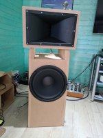
OK, got around 100hrs on the amps, and they are really starting to settle down, to the point where I decided to switch the speakers back to Humble Homemade HiFi Calpamos spec (see photo below). Simply a case of unbolting the mid and treble housings and bolting in the horn section. Change over the crossover board and it's all done.
I was expecting a little more hum / hiss from the horns as they are around 6dB more sensitive than the OBL15's, but I am pleased to say that they are just as quiet. I need to have an ear right up to the horn mouth to hear any hiss, and there is the tiniest bit of hum from the bass driver, but from 3 feet away they are totally silent.
SQ is excellent, clean, clear and dynamic. Ralph will be pleased to know that Chris Squire's Rickenbacker has got most of it's growl back, and I'm perfectly happy with the results.
Having now looked into the Speltz Zero autoformers, I suspect a pair may be winging their way over the pond in a month or two, but for now, very happy with the overall setup, and am enjoying working my way back through my vinyl collection.
Cheers,
Steve.
Attachments
Outstanding! I purchased the zeroes to help the amps drive some low impedance floor standing speakers. (Sometimes you can find the zeros for sale used.) Made a big difference. Speakers now are modified Heresy's (99dB) but left them on as they are transparent to my ears and the amps just loaf along. I have hundreds of hours on mine and they still sound great. About ready to have a tube testing session and make sure everything is up to par.
The Aikido is a good circuit but doesn't support AES48. It should be quite transparent though.
but two aikidos are easily converted to balanced input/output...
but two aikidos are easily converted to balanced input/output...
Have you done it? I bought 2 pcb when i saw him mention about balance in the description. I thought it would be in the manual but there is nothing about it. So I emailed John asking how to config 2 pcb as balance output, but the answer I got was something else explaining the balance but no detail how to ..lol...
Its true but as I said they don't support AES48.but two aikidos are easily converted to balanced input/output...
In a balanced system, ground is ignored. If the output of the circuit is referencing ground, its a real trick to prevent ground loops from being audible. If AES48 is observed, then if ground loops appear they won't cause a problem.
The other issue you're up against is imperfections in the tubes, causing the two outputs to not be entirely equal and opposite. An output transformer solves this, otherwise you'll probably get away with it anyway because the CMRR at the input of the M-60 circuit is pretty decent. But the more you can get away from relying on that the lower the distortion you'll get.
AES48
I can see a pair unbalanced Aikido boards not working but what about the Aikido Balanced design?
The first is the octal. I'm working on a point to point of this one.
The second is the still born noval pcb design.
If one of these won't work, then I have a lot of tubes to sell.


I can see a pair unbalanced Aikido boards not working but what about the Aikido Balanced design?
The first is the octal. I'm working on a point to point of this one.
The second is the still born noval pcb design.
If one of these won't work, then I have a lot of tubes to sell.
Have you done it? I bought 2 pcb when i saw him mention about balance in the description. I thought it would be in the manual but there is nothing about it. So I emailed John asking how to config 2 pcb as balance output, but the answer I got was something else explaining the balance but no detail how to ..lol...
no, what is did was a SY Impasse like, single ended input/balanced outputs i used to dive PASS ACA mosfet amps....
Its true but as I said they don't support AES48.
In a balanced system, ground is ignored. If the output of the circuit is referencing ground, its a real trick to prevent ground loops from being audible. If AES48 is observed, then if ground loops appear they won't cause a problem.
The other issue you're up against is imperfections in the tubes, causing the two outputs to not be entirely equal and opposite. An output transformer solves this, otherwise you'll probably get away with it anyway because the CMRR at the input of the M-60 circuit is pretty decent. But the more you can get away from relying on that the lower the distortion you'll get.
true, you have to get closely matched tubes to implement this...
the whole point of a balanced outputs is so you can have just two signal carrying wires carry the signal and not worry about grounds...
with the aikido, it is also very easy to find closely matched tubes, assuming the cathode resistors are well matched for tolerance, then making sure that the plate voltages of the upper and lower triodes are identical gets you in the ball park...
Last edited:
true, you have to get closely matched tubes to implement this...
the whole point of a balanced outputs is so you can have just two signal carrying wires carry the signal and not worry about grounds...
with the aikido, it is also very easy to find closely matched tubes, assuming the cathode resistors are well matched for tolerance, then making sure that the plate voltages of the upper and lower triodes are identical gets you in the ball park...
The MP-3 circuit does the same thing but with a grand total of two tubes - a 12AU7 and a 6SN7 (the 12AU7 could be replaced with a 6SN7 as well). But it supports AES48.
no, what is did was a SY Impasse like, single ended input/balanced outputs i used to dive PASS ACA mosfet amps....
Thanks, that's a different product. I bought an Octal All-in-One and I am still not sure what he mentioned "The PCB holds two Aikido line-stage amplifiers; thus, one board is all that is needed for stereo unbalanced use (or one board for one channel of balanced amplification)"
Thanks, that's a different product. I bought an Octal All-in-One and I am still not sure what he mentioned "The PCB holds two Aikido line-stage amplifiers; thus, one board is all that is needed for stereo unbalanced use (or one board for one channel of balanced amplification)"
sure you can do that....
- Home
- Amplifiers
- Tubes / Valves
- What tubes for a OTL tube amp?