Correct on both counts. The issue revolves around how your speakers were designed. Part of the reason I produced that article on the link I posted is simply because so many people waste money on equipment matching- with our stuff or anyone elses' for that matter. So, especially in the case of 4 6AS7s, the amp may or may not drive your speaker; IOW some speakers with an impedance curve like that will be a piece of cake to drive and others won't. Its all on the intention of the speaker designer. In a nutshell: if the speaker cannot be driven by an amp that otherwise sounds like real music, then there is no way the speaker will sound like real music. Its that simple.
The speakers should be easy enough to drive since they are full range with no filters at all.
(Jordan fx92s)
(Jordan fx92s)
An externally hosted image should be here but it was not working when we last tested it.
The measured dc resistance of your speakers as found in this thread is 5.3 ohms
Now as anyone can point out im by no means an expert on any of this, but I have seen some people do this in a crossover and it may not be such a great thing.
I found this resistor.
Its 30 Watt with a 2.2Ohm resistance.
in my eyes you should be able to put this in series BETWEEN the speaker and ground. 5.3 + 2.2 = 7.5 Ohm this raises you just below 8 ohms so you shouldnt have to worry about sensitivity loss. Then to keep this from being added to that massive 16 ohm bass response you can calculate an inductor for use as a low pass it will need to be placed in parralel with the resistor to bypass the extra resistance for signals in its pass band.
Judging from your impedance chart i would design the cut off for about 90hz.
With a little bit more work im sure you could work on the lower and upper sides of that hump to flatten the impedance to an average 16 ohm load.
Now before you get too excited wait for someone to post about the cons/pros of this. As i said im not expert but i know if you do that to a dc motor is gets hot and this idea could be damaging to your speakers or the frequency response.
I suppose one could take it even further with a series resistor and a zobel network.
It wouldn't be too hard to tailormake a "perfect" impedance. Othoh it would result in powerlosses in the newly added circuit. I'd rather not take that rout unless I had to.
But we're straying way off target here. This thread is about amplifiers!
Like atmasphere said, it's worth a try.
And adding tubes will lower the source impedance as well as increasing ouput. This should keep one busy for a while I think?
Now for some amp questions...")
+/- 140V (B1) and +/- 300V (B2) seams like standard values for tube psu's.
How much current would they be able to deliver?
I think I read each output tube dissipates up to 2x13W and designing for maximum load (tubes per channel) we get 8*2*13=208W ( 0.7A@300V)
Lets say 20% losses and make it 250W. (0.83A@300V)
And choosing components for 1A should put us in the safe area?
15W (maybe 20W with some to spare?) for the 4 sn7gt tubes?
And then the heaters... what voltages? And how much current? (wattage?)
(It's more stupid not to ask the questions than to ask stupid questions.)
Am I doing this right? Or have I missed some vital stuff? I'm a n0ob and learning as I go along.
It wouldn't be too hard to tailormake a "perfect" impedance. Othoh it would result in powerlosses in the newly added circuit. I'd rather not take that rout unless I had to.
But we're straying way off target here. This thread is about amplifiers!
Like atmasphere said, it's worth a try.
And adding tubes will lower the source impedance as well as increasing ouput. This should keep one busy for a while I think?
Now for some amp questions...
+/- 140V (B1) and +/- 300V (B2) seams like standard values for tube psu's.
How much current would they be able to deliver?
I think I read each output tube dissipates up to 2x13W and designing for maximum load (tubes per channel) we get 8*2*13=208W ( 0.7A@300V)
Lets say 20% losses and make it 250W. (0.83A@300V)
And choosing components for 1A should put us in the safe area?
15W (maybe 20W with some to spare?) for the 4 sn7gt tubes?
And then the heaters... what voltages? And how much current? (wattage?)
(It's more stupid not to ask the questions than to ask stupid questions.)
Am I doing this right? Or have I missed some vital stuff? I'm a n0ob and learning as I go along.
Understand that adding a resistor will not help the sensitivity- resistors don't make sound, they just convert watts to heat. A series resistance will certainly change the frequency response; sometimes that's for the good, sometimes not. See, for example, the "Arpeggio" loudspeaker project, where the inherently high source impedance of an SET amp is used to advantageously increase the bass extension of a closed-box system. That's one reason why OTLs can be controversial- they DO sound different, and much of the difference is due to that high source impedance. For some speakers, the resulting EQ is a positive thing, and those OTL owners are happy. For others... not so much.
I suppose one could take it even further with a series resistor and a zobel network.
It wouldn't be too hard to tailormake a "perfect" impedance. Othoh it would result in powerlosses in the newly added circuit. I'd rather not take that rout unless I had to.
But we're straying way off target here. This thread is about amplifiers!
Like atmasphere said, it's worth a try.
And adding tubes will lower the source impedance as well as increasing ouput. This should keep one busy for a while I think?
Now for some amp questions...
+/- 140V (B1) and +/- 300V (B2) seams like standard values for tube psu's.
How much current would they be able to deliver?
I think I read each output tube dissipates up to 2x13W and designing for maximum load (tubes per channel) we get 8*2*13=208W ( 0.7A@300V)
Lets say 20% losses and make it 250W. (0.83A@300V)
And choosing components for 1A should put us in the safe area?
15W (maybe 20W with some to spare?) for the 4 sn7gt tubes?
And then the heaters... what voltages? And how much current? (wattage?)
(It's more stupid not to ask the questions than to ask stupid questions.)
Am I doing this right? Or have I missed some vital stuff? I'm a n0ob and learning as I go along.
ah my friend i finally do have some truely usefull info for you.
Tubes have datasheets just like transistors one of the largest collections can be found here.
In the american naming scheme models start with a number followed by a product designation that starts with a letter the first number 6,12 denotes the heater voltage but there are exception 300b 845 80 ect.
http://scottbecker.net/tube/sheets/135/1/12JN8.pdf
12.6 volts per tube heater, .3 amps.
Typically people just wire the heaters in parallel
so for 4 tubes your going to need 1.2 amps allow for a 5% deviation from that current draw gives you 1.26 amps so id just as well design the heater part of the psu for 1.3 or 1.5.
If you want more regulation theres LM78 series just pick your voltage and tack it on to the end so you need an LM7812 to regulate positive 12 volts these things have a limit of 1 amp so you will need two for four tubes
this page has a nice set of regulator circuits with the formulas to calculate them for whatever your needs may be Regulators and Power Supplies
If I wanted to build a tube amp without output transformer, what tubes would be a good choice? Lets aim for 20w or something along those lines?
Trust me on this: you do not want a hollow state OTL. If it's an OTL you want, your best bet is to put the hollow state electronics up front driving power MOSFETs on the back end. It'll sound better, and it won't be a room heater.
The vacuum tube is fundamentally a high voltage, low current (Hi-Z) device. Nothing you do will change that. Any OTL will be running into a nearly vertical loadline, and that means just essssssssssss-loads of distortion. You can, of course, correct for that nonlinear operation with gNFB. Why bother? Yes, OPTs are expensive and nonlinear, but they are one helluvalot more linear with a reasonable loadline, and will require much less in the way of correction.
Then there is the efficiency problem. In order to get reasonable power levels into the usual 8R speeks, you will be paralleling a great many VTs. The heater power alone is really gonna add up. I worked up an OTL design that could do some 40W into 8R, using 6BQ6GAs. That required eight 6BQ6GAs per phase (Heater: 6.3V @ 1.2A). I can get that much from a single pair running into a much more reasonable loadline of 1K1 / phase, and matching impedances with a decent OPT. Which would you prefer? I already have my answer.
I like the thought of a single ended amp so I guess that would be on my wishlist as well. But I don't know enough about designing amplifiers to really kno what I'm talking about.
I just want a place to start my reading.
So, a recomendation on suitable tubes and perhaps a topology. That'll keep me busy for a while.
Yes, it helps to know what one is talking about. Take a good look at Technical Books Online -- lots of freebies to download. Depending on where you're at, you might want to check out the Radiotron Designers Handbook.
I think I should point out that I really don't need this amp. I have Musical Fidelities X-A200 monoblocks and I haven't seen a speaker they can't drive.
My newfound interest in tubes are purly for fun.
If in the end it actually sound better than my current set-up, It's a great wonderful bonus.
Of course I want a Kick a$$ sound in the end, but I have time on my side.
My newfound interest in tubes are purly for fun.
If in the end it actually sound better than my current set-up, It's a great wonderful bonus.
Of course I want a Kick a$$ sound in the end, but I have time on my side.
I have looked hard at doing an OTL design with the mentioned tubes, but must admit that I usually end up agreeing with Leadbelly. Seems like a pretty (and $$) heater in the end. (Not taking a side here just struck by how close this thread is to an on-going internal dialog (its sick, I know
And yet these designs are everywhere. And people swear by them. Could some of the OTL supporters answer the question:
"Why bother?" There MUST be a reason. The tubes are impressive -- how much does that enter in? How much heat do these things produce? Are they recommended below the 40th parallel
Regardless of the answer to the why question - I hope a design gets discussed. Hopefully, lower output options might be discussed too -- 80 watts of tube amp seems like a awful lot to me in my small listening room.
I'll take a run at the "Why OTL?" question. But first, let me preface my comments by stating that I'm not trying to instigate a flame-fest over subjective-versus-objective sonic attributes. I firmly believe (and have proven to myself over the years) that good engineering has to be the underlying basis for audio design. Once the engineering fundamentals have been addressed, the subsequent "voicing" of audio components in order to maximum the perceived level of music reproduction is simply the use of the ear as final arbiter in finalizing the audio design. So hold the flames, please...
I built a pair of Rosenblit-based 25W OTL monoblocks and I just love the way they reproduce music, regardless of musical genre being played. A properly-developed tube circuit just audibly preserves more of the music. I haven't seen any objective basis for this stance presented, but once you've heard a really well-developed vacuum-tube audio component, there's no going back... The bottom-line is, OTL's are all about the music.
Really well-designed vacuum-tube preamplifiers (low-feedback, locally-degenerated, balanced, fully-symmetric circuits) can inherently convey the musical essence in our recordings at a performance level that is truly astounding. And we're talking about circuit topologies that present excellent measured performance --- no "magical" circuits that "sound great", but "measure bad". But that brings us to the subject of vacuum-tube power-amplifiers. One of the key limitations of most vacuum-tube power-amplifiers is the set of sonic constraints imposed by the output transformers used to impedance-match the amp and speakers; OTL's eliminate the output transformers, bypassing all of the negative aspects of output transformers. With OTL's, all of the musical nuances are directly coupled to the loudspeakers with none of the sonic artifacts and degradation incurred when employing output transformers.
Most contemporary loudspeaker designs need a fair bit of current to be delivered by the power-amplifier in order to achieve reasonable sound-pressure levels in the listening room. Since vacuum-tubes are (for the most part) current-challenged, a virtual phalanx of vacuum-tubes have to be paralleled to provision the necessary current-delivery capacity. Vacuum-tubes are, relatively speaking, high-voltage power-amplifier output devices. Most OTL's run with a +/- 140VDC dual-rail power-supply, contrasted with a solid-state design's +/- 20VDC dual-rail power-supply, to power a 25W/8-ohms monoblock design. Since power-dissipation equals (current)x(voltage), a comparable standing idle current in the output stage will result in substantially greater heat load for the higher-voltage vacuum-tube OTL as compared with a solid-state design. Due to operational constraints for the vacuum tubes, we can't drop the OTL power-supply rails to the voltage levels of a comparable solid-state design, so the OTL must pay a fairly substantial energy-efficiency penalty to deliver a given level of power output. But, remember, OTL's are all about the quality of music reproduction...
I'm really interested in investigating "atmasphere's" low-feedback, balanced/bridged OTL topology. My current Rosenblit-based OTL's are comprised of cascaded, single-ended gain stages feeding into a "totem-pole" quasi-complementary output stage, all within a relatively high global negative-feedback loop --- while they sound great and measure really well, there's always room for improvement. Through my own series of experimental line-level prototype designs, I've become convinced by what my ears tell me that a low-feedback, fully-symmetric, balanced OTL design has great sonic potential. So I'll be following this thread with great interest and anticipation.
Last edited:
Seconded!I'll take a run at the "Why OTL?" question. But first, let me preface my comments by stating that I'm not trying to instigate a flame-fest over subjective-versus-objective sonic attributes. I firmly believe (and have proven to myself over the years) that good engineering has to be the underlying basis for audio design. Once the engineering fundamentals have been addressed, the subsequent "voicing" of audio components in order to maximum the perceived level of music reproduction is simply the use of the ear as final arbiter in finalizing the audio design. So hold the flames, please...
I built a pair of Rosenblit-based 25W OTL monoblocks and I just love the way they reproduce music, regardless of musical genre being played. A properly-developed tube circuit just audibly preserves more of the music. I haven't seen any objective basis for this stance presented, but once you've heard a really well-developed vacuum-tube audio component, there's no going back... The bottom-line is, OTL's are all about the music.
Really well-designed vacuum-tube preamplifiers (low-feedback, locally-degenerated, balanced, fully-symmetric circuits) can inherently convey the musical essence in our recordings at a performance level that is truly astounding. And we're talking about circuit topologies that present excellent measured performance --- no "magical" circuits that "sound great", but "measure bad". But that brings us to the subject of vacuum-tube power-amplifiers. One of the key limitations of most vacuum-tube power-amplifiers is the set of sonic constraints imposed by the output transformers used to impedance-match the amp and speakers; OTL's eliminate the output transformers, bypassing all of the negative aspects of output transformers. With OTL's, all of the musical nuances are directly coupled to the loudspeakers with none of the sonic artifacts and degradation incurred when employing output transformers.
Most contemporary loudspeaker designs need a fair bit of current to be delivered by the power-amplifier in order to achieve reasonable sound-pressure levels in the listening room. Since vacuum-tubes are (for the most part) current-challenged, a virtual phalanx of vacuum-tubes have to be paralleled to provision the necessary current-delivery capacity. Vacuum-tubes are, relatively speaking, high-voltage power-amplifier output devices. Most OTL's run with a +/- 140VDC dual-rail power-supply, contrasted with a solid-state design's +/- 20VDC dual-rail power-supply, to power a 25W/8-ohms monoblock design. Since power-dissipation equals (current)x(voltage), a comparable standing idle current in the output stage will result in substantially greater heat load for the higher-voltage vacuum-tube OTL as compared with a solid-state design. Due to operational constraints for the vacuum tubes, we can't drop the OTL power-supply rails to the voltage levels of a comparable solid-state design, so the OTL must pay a fairly substantial energy-efficiency penalty to deliver a given level of power output. But, remember, OTL's are all about the quality of music reproduction...
I'm really interested in investigating "atmasphere's" low-feedback, balanced/bridged OTL topology. My current Rosenblit-based OTL's are comprised of cascaded, single-ended gain stages feeding into a "totem-pole" quasi-complementary output stage, all within a relatively high global negative-feedback loop --- while they sound great and measure really well, there's always room for improvement. Through my own series of experimental line-level prototype designs, I've become convinced by what my ears tell me that a low-feedback, fully-symmetric, balanced OTL design has great sonic potential. So I'll be following this thread with great interest and anticipation.
Trust me on this: you do not want a hollow state OTL. If it's an OTL you want, your best bet is to put the hollow state electronics up front driving power MOSFETs on the back end. It'll sound better, and it won't be a room heater.
The vacuum tube is fundamentally a high voltage, low current (Hi-Z) device. Nothing you do will change that. Any OTL will be running into a nearly vertical loadline, and that means just essssssssssss-loads of distortion. You can, of course, correct for that nonlinear operation with gNFB. Why bother? Yes, OPTs are expensive and nonlinear, but they are one helluvalot more linear with a reasonable loadline, and will require much less in the way of correction.
Then there is the efficiency problem. In order to get reasonable power levels into the usual 8R speeks, you will be paralleling a great many VTs. The heater power alone is really gonna add up. I worked up an OTL design that could do some 40W into 8R, using 6BQ6GAs. That required eight 6BQ6GAs per phase (Heater: 6.3V @ 1.2A). I can get that much from a single pair running into a much more reasonable loadline of 1K1 / phase, and matching impedances with a decent OPT. Which would you prefer? I already have my answer.
FWIW there are some fundamental misconceptions here, the first being that all tubes are equal which they are not. From the very beginning of OTL technology in the early 50s, OTLs have used low-impedance tubes. That may sound oxymoronic to some, but we are talking about tubes that handle a lot of current and don't take much plate voltage to do it. Hence: the 6BQ6 above is a poor choice to make power, and the 6AS7G is an easy choice. According to the post above, that's 8 power tubes for 40 watts into 8 ohms. Eight 6AS7Gs can do 60 watts into 8 ohms, and that is running class A.
The 'room heater' thing is a common misconception, based on the idea that lots of tubes make lots of heat, which they don't (they make a little, with the exception being the 6C33 that has a very hot filament). What makes the heat, at least in our amps, is the class A operation. You can run the amps all day in Standby and at the end of the day, grab the tubes and hang on to them without getting burned. But from stone cold, 30 second warmup, and then turn them on- 30 seconds later they are pretty hot! Its the class A that makes heat- so **thats** what makes for a room heater, tube or transistor.
If you run feedback, THD can be in the 0.00?? range at full power. I like to run them without feedback and depending on setup the THD can be between 0.5 to 3% at full power. It always amazes me how many people have the misconceptions seen in the above post- after 30 years I'm still responding to comments like this.
BTW, American 6AS7s can do more power (eight of them will do 80 watts into 8 ohms) but they are the devil to keep running. If you look in the RCA receiving tube manual: 'fixed bias not recommended'... -well that is precisely what we have to do, so you have to use either the Russian 6H13C or the Chinese 6N13 which is their equivalent type. They seem to hold up fine with fixed bias service, as does the Sylvania 6AS7, which is rare.
If you are dead set on using American tubes, it is possible. The cathode resistance must be increased to a minimum of 5 ohms 5 watts (which is a good idea anyway). If the tubes are NOS they must be preconditioned for 72 hours to minimize arcing.
A note on the B+ power transformer! We are not running a bipolar supply. Circlotrons aren't set up that way. They are the only circuit I know of that allows true push-pull without an output transformer and without complementary devices. So you need two equal floating power supplies, so either 2 identical power transformers per monoblock or a unit with dual secondaries.
Each supply will have about 140V output. You'll want each one to be rated at double the idle current at the minimum. In this case our idle current is about 60mA per section, so each supply will idle at 240 mA if 4 power tubes total are used. The supply should be capable of at least twice that under continuous duty.
The 6AS7G has a 6.3V filament that needs 2.5 Amps. You will need a sizable transformer to run them, but I have found them off-the-shelf. For a monoblock just using 4 power tubes, we need 10 Amps continuous. Its nice to have it in a dual secondary, so each phase has its own winding, but its not essential.
so im going to take a stab at both replying to the previous people AND steer this thread back towards developement.
totem poles are a great design but the problem in designing them was mentioned in a page i posted earlier. In a totem pole design like the futterman the signal is essentially split one half of the tubes develope the negative half of the wave while the other developes the upper portion. The problem occurs in a typical totem pole in that the voltage swing of the tube for the negative is different from the positive and thus the incoming signals will need to look like the following image.
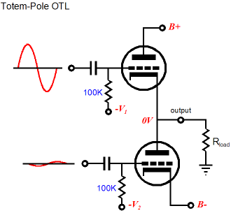
Now back to the design portion the original poster still hasnt publically announced whether he wants to clone atmasphere's design or build his own so ive mocked up a very simple circuit in paint (crude i know but i still havent mastered CAD)
If I recalled correctly when i was drawing this he wanted 4 tubes per channel.
One of the key aspects of this design that might be over looked when someone hasnt done the reading is that this require either a + and - input or a phase splitting stage. Most designs use yet another tube for this but i find for this task in my own opinion that signal diodes would not only be more efficient but more symetrical in performing this particular task. the basics say (just the same as in tubes) that the positive portion of the wave will pass from the cathode to the anode and the negative portion will be blocked and if it is wired backwards the negative portion will flow from the anode to the cathode.
Now these tubes typically have a maximum plate voltage in the 300 range BUT the negative stage has to have the inverse of the plate voltage applied to its cathode. Most datasheets dont tell you what the maximum positive voltage to the cathode is but some datasheets do have two good indicators. 1) this tube is best suited for a grounded cathode amplifier OR 2) the minimum cathode negative in respect to plate positive.
Typically as long as your working with condition 2 and not 1 145 volts should seem to me at least to be a safe voltage.
If your up to some testing / innovation you can still increase the value difference between the plate and cathode.
a variable voltage regulator can be used to apply +/- 20 to maybe... 80 volts positive attached to the plate of the negative amplifier and of course the negative attached to the cathode of the positive. a coupling cap or some other form of dc blocking will need to be applied on the output.
a pot used on the voltage regulators can be used to change the voltage and thus should change the gain.
as a previous person has said tubes can also be used to drive a transistor output stage such as in the starving student amp. also in another design ive seen they modulate the signal, pass it through the OPT and then demodulate on the other side reducing distortion by the OPT
totem poles are a great design but the problem in designing them was mentioned in a page i posted earlier. In a totem pole design like the futterman the signal is essentially split one half of the tubes develope the negative half of the wave while the other developes the upper portion. The problem occurs in a typical totem pole in that the voltage swing of the tube for the negative is different from the positive and thus the incoming signals will need to look like the following image.
Now back to the design portion the original poster still hasnt publically announced whether he wants to clone atmasphere's design or build his own so ive mocked up a very simple circuit in paint (crude i know but i still havent mastered CAD)
An externally hosted image should be here but it was not working when we last tested it.
If I recalled correctly when i was drawing this he wanted 4 tubes per channel.
One of the key aspects of this design that might be over looked when someone hasnt done the reading is that this require either a + and - input or a phase splitting stage. Most designs use yet another tube for this but i find for this task in my own opinion that signal diodes would not only be more efficient but more symetrical in performing this particular task. the basics say (just the same as in tubes) that the positive portion of the wave will pass from the cathode to the anode and the negative portion will be blocked and if it is wired backwards the negative portion will flow from the anode to the cathode.
Now these tubes typically have a maximum plate voltage in the 300 range BUT the negative stage has to have the inverse of the plate voltage applied to its cathode. Most datasheets dont tell you what the maximum positive voltage to the cathode is but some datasheets do have two good indicators. 1) this tube is best suited for a grounded cathode amplifier OR 2) the minimum cathode negative in respect to plate positive.
Typically as long as your working with condition 2 and not 1 145 volts should seem to me at least to be a safe voltage.
If your up to some testing / innovation you can still increase the value difference between the plate and cathode.
a variable voltage regulator can be used to apply +/- 20 to maybe... 80 volts positive attached to the plate of the negative amplifier and of course the negative attached to the cathode of the positive. a coupling cap or some other form of dc blocking will need to be applied on the output.
a pot used on the voltage regulators can be used to change the voltage and thus should change the gain.
as a previous person has said tubes can also be used to drive a transistor output stage such as in the starving student amp. also in another design ive seen they modulate the signal, pass it through the OPT and then demodulate on the other side reducing distortion by the OPT
RK, I'd suspect that what you'd really want is high perveance, which will allow the dissipation to be low as possible for a given current. That does certainly correlate with low impedance but is sui generis. For American tubes, I'd certainly throw the 6528 into the pot (remember, we're homebrewers, we don't have to worry about sourcing for production). My last try at an OTL used 32 of them. There was another oddball, the number of which slips my mind, that was used in the infamous Purple Cow.
bacon665, interesting idea. I think if you use diodes, a 6AL5 is recommended rather than solid state, due to the 0.7V drop for commutation on most silicon diodes. They would introduce a notch distortion, and FWIW OTLs happen to otherwise be immune to notch and crossover distortions unless there are design problems. You might also consider that diodes pretty much force you to run close to class B, which IME does not sound nearly as good.
Sy, the 6528 is OK but has less dissipation than the 6AS7, so you need more of them. The nice thing about the 6528 and other similar variants is you *are* likely to pick them up for next to nothing. I had someone ship me a crate of them for free and he wasn't even a customer. Just figured we could use them
Sy, the 6528 is OK but has less dissipation than the 6AS7, so you need more of them. The nice thing about the 6528 and other similar variants is you *are* likely to pick them up for next to nothing. I had someone ship me a crate of them for free and he wasn't even a customer. Just figured we could use them
It was mentioned earlier that I haven't been very forthcomming about my choicees.
I guess in a way that's true.
Nothing is written in stone and things can always change along the way.
However, as it looks today I'll probably be going with a Atma-sphere M-60 Mk.II.3 clone.
Maybe a reduced number of tubes to save on the electric bill.
But, we have a good discussion going so don't let the thread die just because of me.
FWIW there are some fundamental misconceptions here, the first being that all tubes are equal which they are not. From the very beginning of OTL technology in the early 50s, OTLs have used low-impedance tubes. That may sound oxymoronic to some, but we are talking about tubes that handle a lot of current and don't take much plate voltage to do it. Hence: the 6BQ6 above is a poor choice to make power, and the 6AS7G is an easy choice. According to the post above, that's 8 power tubes for 40 watts into 8 ohms. Eight 6AS7Gs can do 60 watts into 8 ohms, and that is running class A.
The 'room heater' thing is a common misconception, based on the idea that lots of tubes make lots of heat, which they don't (they make a little, with the exception being the 6C33 that has a very hot filament). What makes the heat, at least in our amps, is the class A operation. You can run the amps all day in Standby and at the end of the day, grab the tubes and hang on to them without getting burned. But from stone cold, 30 second warmup, and then turn them on- 30 seconds later they are pretty hot! Its the class A that makes heat- so **thats** what makes for a room heater, tube or transistor.
If you run feedback, THD can be in the 0.00?? range at full power. I like to run them without feedback and depending on setup the THD can be between 0.5 to 3% at full power. It always amazes me how many people have the misconceptions seen in the above post- after 30 years I'm still responding to comments like this.
BTW, American 6AS7s can do more power (eight of them will do 80 watts into 8 ohms) but they are the devil to keep running. If you look in the RCA receiving tube manual: 'fixed bias not recommended'... -well that is precisely what we have to do, so you have to use either the Russian 6H13C or the Chinese 6N13 which is their equivalent type. They seem to hold up fine with fixed bias service, as does the Sylvania 6AS7, which is rare.
If you are dead set on using American tubes, it is possible. The cathode resistance must be increased to a minimum of 5 ohms 5 watts (which is a good idea anyway). If the tubes are NOS they must be preconditioned for 72 hours to minimize arcing.
A note on the B+ power transformer! We are not running a bipolar supply. Circlotrons aren't set up that way. They are the only circuit I know of that allows true push-pull without an output transformer and without complementary devices. So you need two equal floating power supplies, so either 2 identical power transformers per monoblock or a unit with dual secondaries.
Each supply will have about 140V output. You'll want each one to be rated at double the idle current at the minimum. In this case our idle current is about 60mA per section, so each supply will idle at 240 mA if 4 power tubes total are used. The supply should be capable of at least twice that under continuous duty.
The 6AS7G has a 6.3V filament that needs 2.5 Amps. You will need a sizable transformer to run them, but I have found them off-the-shelf. For a monoblock just using 4 power tubes, we need 10 Amps continuous. Its nice to have it in a dual secondary, so each phase has its own winding, but its not essential.
Atmasphere,
I've gotta say that I'm knocked-out by the design elegance exhibited by your OTL topology. I'm a strong adherent to Einstein's precept, "Make it as simple as possible, but no simpler", and in my view, your OTL design is a masterful implementation of this design philosophy.
The M60 OTL is an interesting integration of traditional vacuum-tube design elements that have been synergistically combined with contemporary augmentations. The input/gain stage is quite Zen in its simplified signal-path nature (apologies to Nelson Pass...
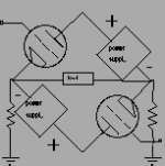
), employing a single-ended differential gain configuration (V1) that is assisted by a cascode configuration (V2) as well as the cascoded current-source (V3) providing the fulcrum for the differential pair (most solid-state designs miss on this means of reducing current-source noise and expanding effective bandwidth). The input stage is a wonderful blending of traditional vacuum-tube design with contemporary op-amp design elements that gets quite close to satisfying the traditional Zen koan asking one to describe the "sound of one hand clapping". The only potential addition to the input stage that would be philosophically-consistent would be the inclusion of a current-mirror active load (I assume that there's some interesting thoughts behind that design decision). The end-result is an amazingly simple signal-path topology; the M60 OTL only needs a single gain stage (augmented with a simple follower circuit) that drives the output stage. Very cool!The M60 OTL conforms to what I refer to as the "iceberg" design approach, in which a very simple, audibly-transparent signal-path "floats above" (and is supported by) a rather substantial, but out-of-band/outside-of-the-signal-path support infrastructure. I didn't really "get" the critical nature of the twin floating power-supplies until I made a couple of simple annotations to the fundamental Circlotron bridged output stage schematic of the M60 OTL; the independent B+/B- power-supplies are literally just two legs of a fundamental bridge circuit (see annotated image culled from the Atma-Sphere Web site). Therefore, the need for robust and audibly-transparent power-supplies becomes obvious within this context. This clarification also eliminated for me about any potential confusion regarding the B+/B- power-supplies; this dual-rail power-supply configuration is simply the means of enabling a DC-coupled output stage (I assume the grounded 600-ohm resistors spanning the output provide a ground reference for the output stage). Again, wicked cool!
It looks like it would be reasonably straight-forward to scale-up/scale-down the output power by varying the number of pairs of tubes in the output stage, correct? If so, what's the limit on how may output tube pairs can be properly driven by the gain-stage follower (V4)? Would it be rational to parallel the gain-stage follower to increase the number of output pairs that could be driven?
A couple of additional questions; is the per-triode 60 milli-ampere output-stage bias current for the Class-AB mode? If so, what is the Class-A mode bias current?
Again, thanks for sharing the knowledge with the DIY community!
Attachments
Actually the Einstein amp is based on this approach not out of coincidence. However they use feedback; consequently on the right speaker this amp sounds better, and it is certainly more reliable, since we don't have 6C33s (we've been selling into the German market since 1990).
We implemented the first version of the voltage amplifier in 1985 so it predates Nelson by a few years. The CCS is a big deal- being 2-stage it allows the gain the 6SN7 sections to reject power supply noise and set up the current for the differential amplifier. Over a range of 100 to 128V with an unregulated supply the performance of the voltage amplifier is unaffected.
I should stress that it is important also to get the noise down on the plate of V4 for best results. We often bypass it with 200uf.
There are, IMO, no good implementations of a tube-based current mirror. They all dramatically reduce the gain without helping out distortion. OTOH the CCS won us so much extra performance that it was a no-brainer. BTW, by paralleling extra tube sections on the bottom you can decrease the plate load resistor to 1/2 or less of the value shown and get greater bandwidth, lower distortion and more gain all at once (usually you sacrifice one to get the other two). Of course the cathode resistor of the CCS would have to be adjusted to best gain/distortion at full whack.
I forgot...
About the bias- 60 ma per section is class A2 with this circuit, due the grid current capabilities of the driver. With the plate voltage and this idle current, the tubes will not cut off without the amp also clipping.
You could run a little more current and less B+, as little as 100V.
Its possible to implement the amp with a different driver. We used a fully differential cascade circuit before 1985 (this was similar to what BAT used in the VK-60; Victor's business partner was a customer of ours before they went into business together). You get less power as the driver saturates with grid current and I don't see the point of that (if you have 6C33s, its not so bad because the grid saturation curve looks like a pentode on that tube so a really beefy driver won't win you a whole lot of extra power). Plus the cascade circuit requires matched tubes (which is how we did it and how BAT did it) or you have an extra set of coupling caps. However you have to use coupling caps between the driver and the power tubes, and that leads to real bias stability issues!
This is important for overload recovery, this amp has instantaneous overload recovery and you don't need such big coupling caps, so its easier to get it to sound right.
- Home
- Amplifiers
- Tubes / Valves
- What tubes for a OTL tube amp?