I have a circuit diagram for a tube phono stage (Audio Innovations 500 ) using a pair of ECC83s. I also have a Chinese phono stage pcb using a pair of 5670s which frankly sounds abyssmal. The actual circuit is quite similar to that for the ECC83s. I'm thinking of stripping the components off the Chinese board and building up the Audio Innovations circuit but keeping the 5670s as the pinouts for the two valves are very different. I'm just trying to use stuff that I already have and hell, it's good fun anyway ")
The electrical characteristics for the two valves are not that different apart from Ra which is 80,000 for the 83 but only 6,400 for the 5670.
Can anyone advise me on this or has anyone any comments.
I'll try and post the circuit diagrams if I can but I tried this morning and I was struggling for some reason.
I suspect that the 5670 / 2C51 / WE396A might not give the best performance at the very low currents typical in ECC83 / 12AX7 circuits.
Gain is a is a little lower than ECC83, and I would say it is more like a ECC81 / 12AT7.
If you want to "clone" the AI RIAA you shoulod probably try to use the same tubes.
SveinB.
Gain is a is a little lower than ECC83, and I would say it is more like a ECC81 / 12AT7.
If you want to "clone" the AI RIAA you shoulod probably try to use the same tubes.
SveinB.


Those 2 circuits are completely different "animals". The AI circuit uses passive equalization, while the 5670 uses active equalization inside a NFB loop.
Frankly, I'm unenthusiastic about the AI circuit, in an unmodified state. The drive capability of the 'X7 triode is POOR.
Frankly, I'm unenthusiastic about the AI circuit, in an unmodified state. The drive capability of the 'X7 triode is POOR.
Those 2 circuits are completely different "animals". The AI circuit uses passive equalization, while the 5670 uses active equalization inside a NFB loop.
I understand that, I think what I was getting at was that I could adapt the Chinese board to the AI circuit reasonably easily as long as I left the 5670s in.
Frankly, I'm unenthusiastic about the AI circuit, in an unmodified state. The drive capability of the 'X7 triode is POOR.
Can you expand on that and would the AI circuit work with 5670s instead of ECC83s with maybe some changes to some component values?
Can you expand on that and would the AI circuit work with 5670s instead of ECC83s with maybe some changes to some component values?
The 'X7 triode is high RP and it runs at very low current. Both of those factors make it a POOR driver of downstream loads. The "classic" RCA circuit, which the AI is a variation on, requires the downstream load to be not less than 250 KOhms.
"Can't fight its way out of a wet paper bag."You certainly can use passive EQ with 5670s. The "lumped" EQ method both RCA and AI employed is well understood. However, 5670 μ is only 35. That suggests CCS loading is needed to get sufficient gain. O/P impedance will be lower than that obtained with a 'X7 section, but is still likely to be troublesome. A buffering voltage follower at the O/P is (IMO) in order.
Frankly, I have my doubts about turning the sow's ear into a silk purse.
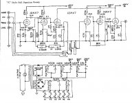
That 5670 circuit reminded me on the MingDa 767, I rebuilt mine to use 6DJ8, and used this circuit; RJM Audio - Tube passive phono preamplifier with better result.
Arne K
Arne K
Thanks Arne, I appreciate the post. It could be similar to the Ming Da. It's a Lite Audio CT-2.

The reason I wanted to stick with the 5670s was so I could re use the board as the pinouts for ECC88s and 83s are very different. Eli D reckons the AI circuit is flawed and I'll go along with that. I'm no electronics engineer so I need all the help I can get from you guys.
If I was to go with the circuit in the link you posted Arne, maybe I could remove the valve bases from the CT-2 board and make up some L brackets and put the bases on their side. I can then wire any pin to any hole in the board. Or should I should start afresh with the valve bases on an L bracket and hard wire? I'll think about that one.
I like the idea of 6DJ8/ECC88 as my power supply has 12.6 volts @ 500 mA for the heaters so I could put the valve heaters in series The specs say 6.3 volts A @365 mA for the 88 so that should be good and I can keep the original power supply.
How did your rebuilt phono stage sound? We're you happy with it?
Si.
The reason I wanted to stick with the 5670s was so I could re use the board as the pinouts for ECC88s and 83s are very different. Eli D reckons the AI circuit is flawed and I'll go along with that. I'm no electronics engineer so I need all the help I can get from you guys.
If I was to go with the circuit in the link you posted Arne, maybe I could remove the valve bases from the CT-2 board and make up some L brackets and put the bases on their side. I can then wire any pin to any hole in the board. Or should I should start afresh with the valve bases on an L bracket and hard wire? I'll think about that one.
I like the idea of 6DJ8/ECC88 as my power supply has 12.6 volts @ 500 mA for the heaters so I could put the valve heaters in series
The specs say 6.3 volts A @365 mA for the 88 so that should be good and I can keep the original power supply. How did your rebuilt phono stage sound? We're you happy with it?
Si.
Thanks Arne, I appreciate the post. It could be similar to the Ming Da. It's a Lite Audio CT-2.
The reason I wanted to stick with the 5670s was so I could re use the board as the pinouts for ECC88s and 83s are very different. Eli D reckons the AI circuit is flawed and I'll go along with that. I'm no electronics engineer so I need all the help I can get from you guys.
If I was to go with the circuit in the link you posted Arne, maybe I could remove the valve bases from the CT-2 board and make up some L brackets and put the bases on their side. I can then wire any pin to any hole in the board. Or should I should start afresh with the valve bases on an L bracket and hard wire? I'll think about that one.
I like the idea of 6DJ8/ECC88 as my power supply has 12.6 volts @ 500 mA for the heaters so I could put the valve heaters in series
How did your rebuilt phono stage sound? We're you happy with it?
Si.
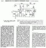
"A picture is worth a 1000 words." The photo provided shows what appears to be a full function preamp, as too much stuff is present on the 2nd PCB to be merely a PSU. Another photo of the jack set, from the outside, could be informative too.
A LOT of work will go into changing the RIAA PCB. The "surgery" involves (among other things) cutting traces, drilling holes, adding jumper wires, and drawing traces with a special pen that contains a Silver bearing composition. Moving away from the 5670s adds very little to the effort.
For the life of me, I can't fathom why people are surprised when inexpensive Chinese guano turns out badly.

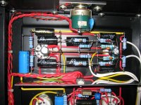
The board on the left is the psu, the board on the right is the phono stage. I built it into an old amp case that had gone to Jesus big time LOL.
Yes you're probably right Eli, it's maybe best to start again.
I can't argue about it being cheap Chinese rubbish but some of the parts are very good. The boards are well made. I suppose if I'd paid good money for them I'd deserve all I got, but as they were given to me I thought I might as well have a play around with them.
The guy same gave me the two boards for a full function preamp as well which I've built up and that does sound quite good indeed, good enough to keep in a second system
Your phono stage circuit ticks most of the boxes Arne so I think I'll give it a go.
Si.
If you are starting from scratch, take a look at the tweaked version of the RCA preamp I had a hand in. The tweaks address the 2 biggest weaknesses of the RCA original: poor drive capability and mediocre bass extension. Yes, you could graft the MOSFET source follower onto AI's circuit too. If the tweaked RCA setup is of interest. Look here and follow the links. Some parts value changes are in order.
Attachments
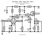
I'll be immodest. One builder's remark was "incredible".
I claim no more than competence. Some MM carts. and SUTs fair poorly working into the large CMiller of a 'X7 section. OTOH, given a compatible "5" mV. signal, the tweaked RCA circuit will make you smile.
Never forget that all passive EQ phono preamps are descended from RCA's original. The 7025 is a 12AX7/ECC83 equipped with a spiral wound, hum bucking, heater. Of current production tubes, the Sovtek 12AX7LPS is the variant that meets the description.
One builder's remark was "incredible".I claim no more than competence. Some MM carts. and SUTs fair poorly working into the large CMiller of a 'X7 section. OTOH, given a compatible "5" mV. signal, the tweaked RCA circuit will make you smile.
Never forget that all passive EQ phono preamps are descended from RCA's original. The 7025 is a 12AX7/ECC83 equipped with a spiral wound, hum bucking, heater. Of current production tubes, the Sovtek 12AX7LPS is the variant that meets the description.
Attachments
Thanks Svein, but I think I'll go down the hard wire path. It's fairly simple to do and it'll be interesting I think. I'm not knocking those Chinese boards but the circuits are modified and I'm not sure they deliver sonically.
So for starters I'm going build the phono stage suggested by Cobra2 for no other reason than I have most of the bits and it's easy for me to do. When that's up and running I'll turn my attention to your phono stage Eli. I think yours needs more attention to detail though to get it right and that's why I'm going to do the other one first. I should have something sorted in a day or two
So for starters I'm going build the phono stage suggested by Cobra2 for no other reason than I have most of the bits and it's easy for me to do. When that's up and running I'll turn my attention to your phono stage Eli. I think yours needs more attention to detail though to get it right and that's why I'm going to do the other one first. I should have something sorted in a day or two
I don't mean to throw a wrench in your plans since you have spent so much time thinking about them, but in my opinion the 1st thing you should do is turn this thread into a "how should I fix my Chinese 5670 phono stage thread?". Frankly, that 5670 circuit looks fine to me, other than the glaring weakness of lack of an output buffer. Try sticking a 5670 or 6DJ8/ECC88 cathode follower on the end and see what it sounds like. If still sounds bad, I would suspect PS issues. Sure, you can get caught up into chasing higher performance circuits with CCS's and passive EQ and so on, but IMHO you are already 50% there with that phono stage.
Try sticking a 5670 or 6DJ8/ECC88 cathode follower on the end and see what it sounds like.
If you put the voltage follower inside the NFB loop, something that resembles the Marantz circuit is the result. FWIW, ARC uses that general style too.
IMO, implementing a DC coupled ZVN0545A source follower will prove LESS problematic than adding an additional tube. For starters, both heater power and space are non-issues.
Thanks for that Leadbelly. Don't worry about throwing a spanner in the works, that what we're here for. I did consider that approach but I'd been led to believe that the 5670 route was not worth persueing ( not on the forum I add) hence my looking at alternatives. Eli is correct that I dont have enough heater current to run another tube and I want to keep the psu that I have. I suppose I could find room for the mosfet though Eli.
Whilst we're on the subject of buffers, the circuit put forward by Cobra2 has no buffer stage so am I going to have the same problem with that?
Time for a rethink maybe.....
Whilst we're on the subject of buffers, the circuit put forward by Cobra2 has no buffer stage so am I going to have the same problem with that?
Time for a rethink maybe.....
- Status
- This old topic is closed. If you want to reopen this topic, contact a moderator using the "Report Post" button.
- Home
- Amplifiers
- Tubes / Valves
- 5670