Hi TM,
thanks for the links, I will read them through.
As for the PSU I think Eli put it quite well and the voltage is not that exact thing, 450-475 is a healthy and realistic range.
Rich,
I agree with you about the CCS, I had already thought about redesigning it and a LED will be a good choice, they are also low noise.
I'm not too worried about temp.co, it will probably be quite stable when everythng have warmed up and settled.
Cheers Michael
I read in later posts that the CCS in the schematic did not work properly. I'm interested in the Supertex mosfets for this use. I wonder in these K&K modules would just "drop in". I'm afraid I know little about modern sand.....
K & K Audio - Lundahl Transformers, audio DIY kits and more
K & K Audio - Lundahl Transformers, audio DIY kits and more
Last edited:
TM, what post was that about the CCS didn't work so well.. I just made a quick calculation on it and at 6 mA the voltage at the Cathode can't get below 3,5 Volt from above Ground as the CCS stops to work as such if going below.. if I recall my memory correct as it was for a little while I did the calc..
yes those ready made CCS from K&K are ready to drop in and the minimum voltage over them was 4 Volts so they will be able to go even below Ground voltage if they are tied to the -6.3 V rails as in the zafir1981s schematic.
I just wonder what would other think of a second CCS on the KT88 pair or is that overkill?")
Cheers Michael
yes those ready made CCS from K&K are ready to drop in and the minimum voltage over them was 4 Volts so they will be able to go even below Ground voltage if they are tied to the -6.3 V rails as in the zafir1981s schematic.
I just wonder what would other think of a second CCS on the KT88 pair or is that overkill?
Cheers Michael
Last edited:
I think it was the link labeled "Amp layout". As to CCS on the output stage, i've heard bad bad things!
Anyone game to sketch out a PS schematic for this project. Something basic like the last one Eli proposed. I'm studing the Morgan VA book, but don't think anyone here would want a amp using any PS I could design. A BOM also needs to be formulated. I'm not sure of resistor wattage ratings, and capacitor types / brands. I want to use higher grade parts, but skip the $200 capacitors. I have an assortment of Dale metal film resistors to start! UT, perhaps you have some thoughts?
Anyone game to sketch out a PS schematic for this project. Something basic like the last one Eli proposed. I'm studing the Morgan VA book, but don't think anyone here would want a amp using any PS I could design. A BOM also needs to be formulated. I'm not sure of resistor wattage ratings, and capacitor types / brands. I want to use higher grade parts, but skip the $200 capacitors. I have an assortment of Dale metal film resistors to start! UT, perhaps you have some thoughts?
Last edited:
Ok I found the dwelling about the CCS, well as I see it it was just some minor concerns, but would you still feel safer with a ready made CCS module K&K?
It's just 2 legs you have to solder in I think so one can't fail too much on that one.
btw I wasnt too correct when mentioning about the drive stages cathode voltage over the CCS, there's plenty of headroom as the cathode voltage will be maybe 100 Volts up or maybe little bit more, but no worries the current needed from CCS is so small so the power development isn't any gross.
Choice of Cs and Rs, for caps I would go with red WIMA MKP (Polypropylene), that's a sure bet and these are transparent and stable and doesn't add much of its self to the sonic, eg. "invisible".
http://www.wima.com/EN/WIMA_MKP_4.pdf
Resistors I'm not really sure of yet which brand and what type, but one type for sure have to stand outside is the carbon comp resistor, actually they are even dangerous if they start to burn they will flame pretty well, and couple of other reasons too not worth to mention.
Final values and wattage has to be calculated, I am about to start dig in my head into the toob-cook-books so it will take some time before I can calculate anything, tubes aren't that much different from any other type of gain devices like BJTs and mosfets.
The PSU will depend on the final amp drawing, eg when the working points for all tubes are defined and all voltage/current/resistor values are calculated, then we can look at the PSU as from what I have seen is used for tube amps are the sc. "voltage regulation" is pretty crude.
So if we do the ol' toob-way it means burning up power in a series resistor to reach the correct voltage fall and that is dependent on the quiescent current, plate resistors and so on as far as I understand it for now, so that's why it's not that straight forward and, well.. for those who are little bit more engineering mind oriented who like to calculate and estimate and source the "perfect" cap or res is also part of DIY and that is very time consuming so things can some times go a bit slowly and better to not expect to much of the time schedule.
As far as I see it for now the main priorities are:
1. calculating the new working points for a lower B+ voltage (~460V) and eventually new working points for input/drive stage.
2. find a OPT
Regarding the OPT I'm still pondering over the role of DC resistance on the primary side, which I think will have some role of the quiescent current through the KT88s, will check that closer.
btw the KT88 can be bought already now that's for sure, have you found any source where to buy a quad matched set and any brand preference?
If not I found some guy on eBay selling quad matched set of the brand Electro Harmonix and that's what I'm going for, the cryo treated hypo NOS for US$ ++X00 will I leave fore somebody else.
Ok time for break..
Cheers Michael
Last edited:
Hey guys,
I'm currently building a KT88 PP Ultralinear amp, too.
Although it's gonna be on a different circuit style, I had to look for OPTs too and finaly settled with someone, who is registered in this forum and impressed me with his detailed and dedicated answers in past OPT threads.
I'm talking of Bud Purvine of O/Netics (hpurvine at gmail dot com). I tend to appreciate people who take the time to help others without marketing themselves. And so, although I have to pay a lot of shipping costs from the US to Europe, I ordered OPTs from him. I'd advise you to at least consider him, the contact is very nice, fast and informative.
I can't say much about WIMA in tube amps, but in all the many applications I used them in, they always performed without any problems, so I'd recommend and use them any time. The MKP10 is said to even be a very nice coupling cap, although not the very best. But certainly a very good value for the money.
As for the tubes, I researched very carefuly on that matter and it seems that Reflector makes the best in-production KT88, which means Electro Harmonix or Gold Lion. I am going to buy EH, since JAC says that internals and measured data suggests that they are pretty much the same thing and EH is much less costy...
Last edited:
It's KT 88's alround.
This is my build i'm starting Patrick Turner design 85 watts with a heap of class A. I don't have the iron but do have the components. I'm using mullard AU7 phillips EL84's and either EH or the genelex reissue. Building them on dual mono chassis.
The PSU and protection circuit will be built on 2.4MM PCB all other circuit hard wired maybe using some Keystone turret strips on the 3 mm ge material.
How much space should i allow around the KT88's?
. This is my build i'm starting Patrick Turner design 85 watts with a heap of class A. I don't have the iron but do have the components. I'm using mullard AU7 phillips EL84's and either EH or the genelex reissue. Building them on dual mono chassis.
The PSU and protection circuit will be built on 2.4MM PCB all other circuit hard wired maybe using some Keystone turret strips on the 3 mm ge material.
How much space should i allow around the KT88's?
Attachments
Guys,
Here's the deal with the 12AT7 LTP: 200 to 220 V. on the plate and IB = 3 mA. sounds GOOD.
You can buy the cascode CCS from K/K or you can use what we did in "El Cheapo" and save a few coins. Check Jim McShane's site out. AAMOF, you may be able to get away with the 10M45S IC.
Don't be fooled by appearances. The "reissue" GEC tube IS better than the EH tube. However, the EH tube is an excellent value.
It's likely that a single negative supply can take care of both O/P bias and the LTP tail. A good CCS will "eat" many Volts, if necessary.
Guys,
Don't be fooled by appearances. The "reissue" GEC tube IS better than the EH tube. However, the EH tube is an excellent value.
AH- ha, Whats the "betterness" about the reissues. pse elaborate ?
richy
Anyone game to sketch out a PS schematic for this project.
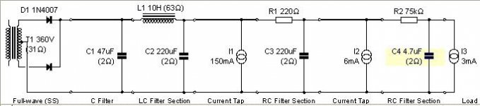
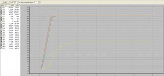
Here is my semi-newbie attempt at a PSUD model for the PS, with the following assumptions:
assumption 1: B+ for KT88 output tubes is 465V @ 75 ma/tube (150 ma for a monoblock pair)
assumption 2: B+ for 12AT7 is around 460V @ 6ma for both sides total. Tubemack, the schematic that you sent me shows 480V B+ for 12AT7 with a KT88 B+ of 520V-I am assuming that you want to end up with a KT88 B+ around 460V..so this would drive a slight reduction in the values of the matched pr of 56K anode load R's to get back to 3 ma/side, unless the B+ for the 12AT7 was the first tap, probably not a good idea for ripple, etc.
assumption 3: B+ for the EF86 is 240V @ 3ma
The ripple voltage for the KT88 B+ is 10mv, the remaining B+ voltages are flatter than a pancake.
Current tap I1 is the 460V for the KT88 pairs, I2 is 460V for the 12AT7, and I3 is the tap for the EF86.
The power transformer is an Edcor XPWR002 (360-0-360 @ 220 ma), vertical mount, and very affordable. There are other possibilities, such as the Triode electronics PA135 (370-0-370 @ 150ma), although that may be marginal.
The diodes are Fairchild 8A 1200V Stealth (Mouser P/N ISL9R8120P2) bypassed with 2KV 10nf ceramic caps (other suggestions welcome). The vanilla 1N4007s shown are a PSUD limitation.
The caps are all Panasonic TS-UP series (500V) or other 500V rated caps. IIRC Allied electronics sells Cornell Dublier 500V electros as an alternative. The Panasonic TS-HB series may work, but are on the ragged edge for overvoltage during startup (360V x 1.41=507V). The 450V TS-HB is rated for 500V surge, and the TS-UP is rated for 550V surge. You could always stack lower voltage caps in series with suitable bypass R's..
The choke is a Hammond 193M (10H @300 ma, 63 ohm R)
If any of the above volts/ma need to be tweaked, please post and I'll update the PSUD model.
I'm assuming that the bias neg rail will be provided by another transformer..
Are you planning on a delayed start-up scheme? If so, separate heater and bias transformers are handy for that.
TubeMack: Since the link for option 1 in your first post appears to be broken, perhaps you could post the schematic?
Attachments
Last edited:
The diodes are Fairchild 8A 1200V Stealth (Mouser P/N ISL9R8120P2) bypassed with 2KV 10nf ceramic caps (other suggestions welcome). The vanilla 1N4007s shown are a PSUD limitation.
UF4007s are drop in replacements for 1N4007s that are much quieter. The 10 nF. snubber value works here too.
The 'T7 sounds GOOD, with a 200 to 220 V. plate to cathode differential and IB = 3 mA. You can use the "check valve trick" we used in "El Cheapo" to minimize decoupling network losses. That allows good sized LTP load resistors.
Adding a CL150 inrush current limiting thermistor to the B+ supply delays rail rise for a few seconds. That's enough time for the instant on bias supply to provide electrostatic protection against cathode stripping.
The AnTek AN-2T350 toroidal power trafo costs $35 and it rates to prove satisfactory. Parallel the 2X HV secondaries and bridge rectify. A nice tweak here is to use snubbed UF5408s on the ground side of the bridge and 3 A./600 PIV Schottkys on the "hot" side. This setup is as quiet as vacuum rectification, while being economical.
Caps. are less costly than power magnetics. Use good sized caps. in a CLC filter and the $16.18 (from Allied) Triad C-17X 1.5 H./300 mA. choke. A way to blacken the background is to insert a "hash" filter made of a RF choke and a 1000 pF. NPO ceramic cap. between the 1st filter cap. and the main inductor.
Attachments
Here's the current Schematic i'm building from. Any final tweeks or sugguestions are welcome.
I'd like to thank Boywonder for helping with the PS. Also a thanks to Eli, and the others for all the good suggestions!
Here's where i'm at:
I took a few days off to complete my tube reference library, and purchase a new Rigol DSO to complete my test gear setup. I should have everything I need now to do fairly extensive testing on the the project. I now just need to make sure the schematic is locked down, and the PS is complete. Any suggestions on specific componet types /brands are greatly appreciated! I want to go with all excellent stuff just short of those $100 each capacitors! I've been studing my Morgan book, but will still need much help. The chassis will be a standard wood frame / top plate design. After the transformers are bought, i'll start design of the top plate using Front Panel Express, (I'm farming it out to them). I may try my hand at the wood frame. I'm purchasing the black walnut this week.
As to the PS, I like it! I do want to stay with the standard transfomer, but i like that hash filter Eli mentioned. I like black backgrounds! The inrush filter is a go too.
An externally hosted image should be here but it was not working when we last tested it.
I'd like to thank Boywonder for helping with the PS. Also a thanks to Eli, and the others for all the good suggestions!
Here's where i'm at:
I took a few days off to complete my tube reference library, and purchase a new Rigol DSO to complete my test gear setup. I should have everything I need now to do fairly extensive testing on the the project. I now just need to make sure the schematic is locked down, and the PS is complete. Any suggestions on specific componet types /brands are greatly appreciated! I want to go with all excellent stuff just short of those $100 each capacitors! I've been studing my Morgan book, but will still need much help. The chassis will be a standard wood frame / top plate design. After the transformers are bought, i'll start design of the top plate using Front Panel Express, (I'm farming it out to them). I may try my hand at the wood frame. I'm purchasing the black walnut this week.
As to the PS, I like it! I do want to stay with the standard transfomer, but i like that hash filter Eli mentioned. I like black backgrounds! The inrush filter is a go too.
Last edited:
I found the teflon caps from russia on EBAY look promising. I mostly used 2 watt resistors (welwyn) excpet where disspiating more power. I'd be keen to hear more on the difference between the two KT88's.
For my power supply i have designed PCBS to accomodate snap in electros, discrete diodes for the bridges (P600 & P1000) and the 5 wattt zeners. I also found some 1 watt trimpots by meggit (Tyco) so made up a little board so i can adjust them through the top of the chassis.
I orginally intented to hard wire everthing, but the cost of the electros with screw terminals is significantly more than the pcb types. Ketsyone have some nice terminal boards and turret strips. I'm going to make my own from teflon insulated turrets mounted on 3 mm fiberglass pcb material.
In Aus the iron is rediculoulsy expensive. I have been quoted AU$350 for each power transformer, AU$150 for each psu choke, AUD $160 for each driver choke and AU$300 for each OPT.
Dual mono better be worth it!!
Last edited:
In the CCS, replace that lower BD139 with BC549C and the two small signal diodes with a single red LED. Rccs seems unnecessary - that 6mA isn't critical. You could remove it and just set the 6mA by checking you have roughly 150V dropped across those 56k anode resistors. What is the purpose of R18?
What is the purpose of R18?
Presumably to save the tubes if bias pots fail.
If i were to build this i would use a different CCS which doesn't require a negative supply.
As to the PS, I like it! I do want to stay with the standard transfomer, but i like that hash filter Eli mentioned. I like black backgrounds!
The "hash" filter is important, when large value cap. I/P filters are employed. A large 1st filter cap. is associated with a small conduction angle and a very sharp, "triangular", ripple waveform. Fourier's Theorem tells us that such a waveform contains overtones of the ripple fundamental extending well up into RF. The many turns of wire in a PSU filter choke create sufficient capacitance to short the choke out at RF. The LC section made from RF components ("hash" filter) "dulls" the ripple waveform down, which permits the main inductor to do its job well.
If i were to build this i would use a different CCS which doesn't require a negative supply.
Agreed, I want to simplfy the CCS, and use a basic simple Cascode using Supertex mosfets with no external supply. Can anyone draw this up?
Eli, Can you name a specific RF choke for the hash filter? Also, you prefer the UF4007 over the ISL9R8120P2?
Other than the hash filter, and thermister, is the PS now a go?
Last edited:
TubeMack: With a B+ of 520V, what current are you planning on running the KT88's at?
I am re-doing the PSUD model and with a 520V B+; you'll have to stack some caps to get sufficient dialectric strength from the electrolytics. The Triode Electronics P 782 S power transformer looks good for this B+, and it has a 70V bias tap. It's a clone for the Dynaco MkII/MkIII. There is probably also an Edcor Model that will fit the bill also.
I'll post another PS schematic shortly.
You can get away without a B- supply under the CCS, IF enough Volts (about 30) to operate the CCS and to provide compliance with the I/P drive signal are available. The LTP's driven grid is DC coupled to the EF86's anode and is at the same potential. Therefore, at "idle", the cathodes will set up at a somewhat higher potential consistent with the forced IB and the LTP anode potential. Are enough Volts left to operate the current sink and provide compliance? If not, changing to a depletion mode MOSFET cascode as the CCS will not eliminate the need for a negative rail. FWIW, I prefer the FET cascode CCS as it's simple and very effective.
For the PSU "hash" filter you select a RF Choke that can comfortably handle the DC draw, without saturating. Long time coil winder J.W. Miller is still on the job and Mouser carries their production. The Mouser catalog page for Miller RFCs is here. Mouser stock # 542-5800-152-RC looks good to me.
For the PSU "hash" filter you select a RF Choke that can comfortably handle the DC draw, without saturating. Long time coil winder J.W. Miller is still on the job and Mouser carries their production.
The Mouser catalog page for Miller RFCs is here. Mouser stock # 542-5800-152-RC looks good to me.- Home
- Amplifiers
- Tubes / Valves
- Mullard 5-20 KT88 PP blocks!